3OM-1345-006_w.pdf - 第256页
6-25 AKHEDT -ID 2.1.9 Head Rotational Angle Axis Offset When the "Head" tab is pressed in the "Device Offset" tab sheet and the "Hd Rotate Axis" tab is selected, the following tab sheet appe…
6-24
AKHEDT-ID
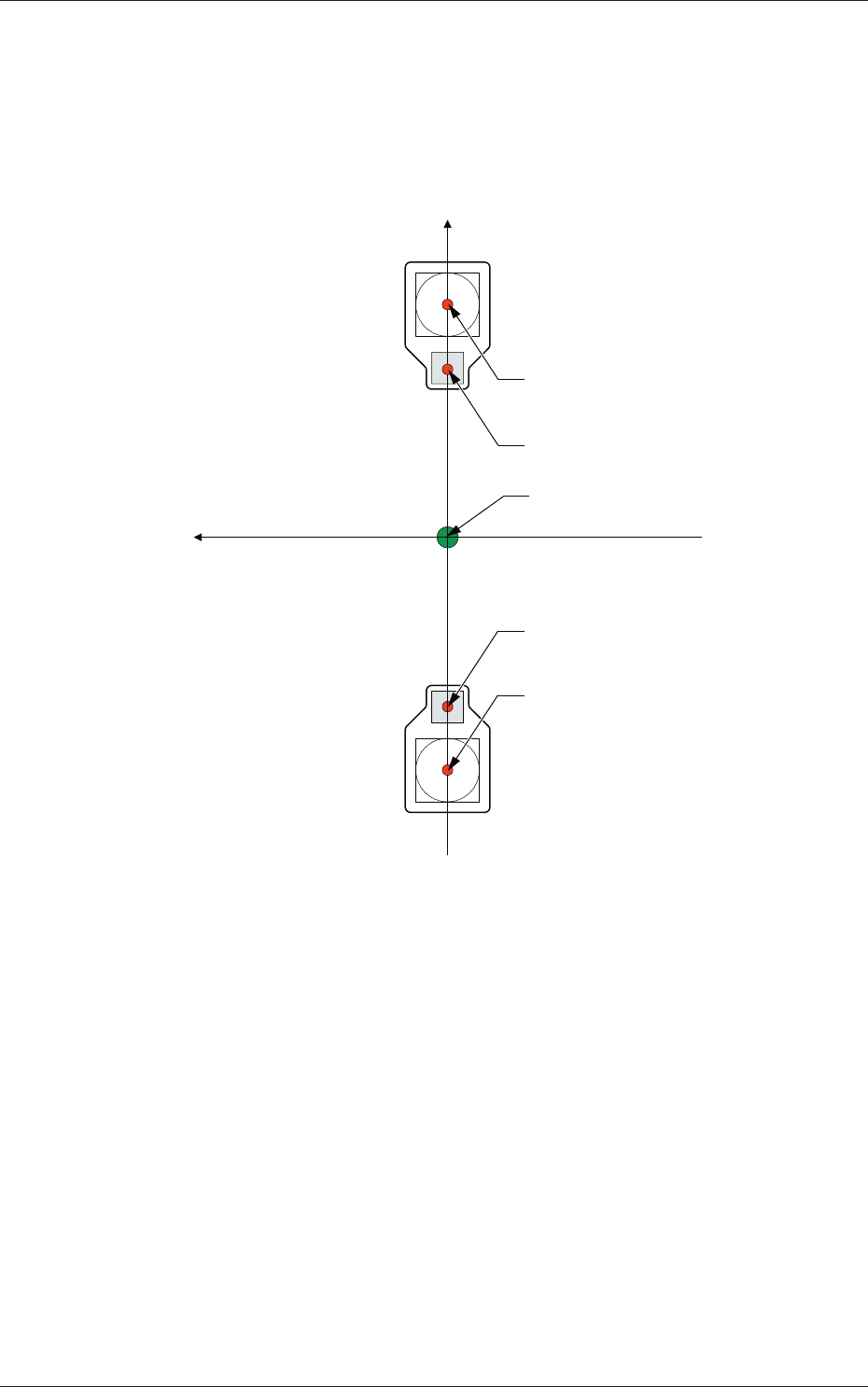
Head 1 and Head 2
X (Horizontal), Y (Vertical) [mm]
The set parameters are used to adjust the deviations in the design value
between the head rotational center and the center of the PEC recognition
camera.
Xm (+)
Ym (+)
Xm-Ym : Machine Reference
Coordinate System
Center of PEC Recognition Camera
Center of PEC Recognition Camera
Head Rotational Center
Head Rotational Center
Pm. Machine Reference
Coordinate Origin
Fig. 3F20
0602-001
2.1 Device Offset Data
6-25
AKHEDT-ID
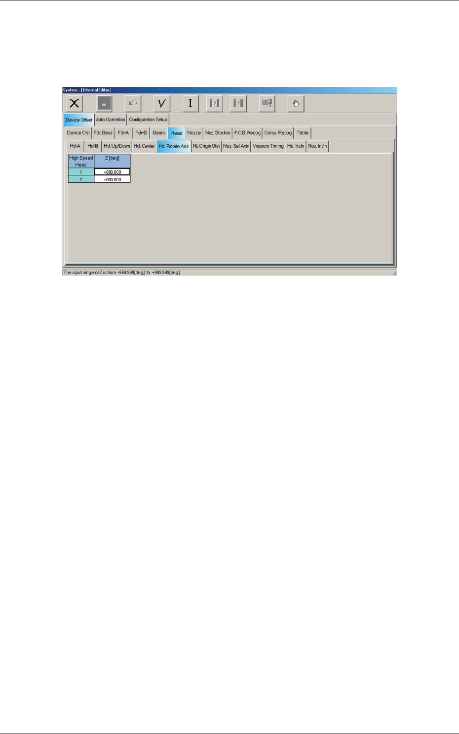
2.1.9 Head Rotational Angle Axis Offset
When the "Head" tab is pressed in the "Device Offset" tab sheet and the "Hd
Rotate Axis" tab is selected, the following tab sheet appears.
Fig. 3F21 "Head Rotate Axis" Tab Sheet
0609-002
2.1 Device Offset Data
6-26
AKHEDT-ID
0602-001
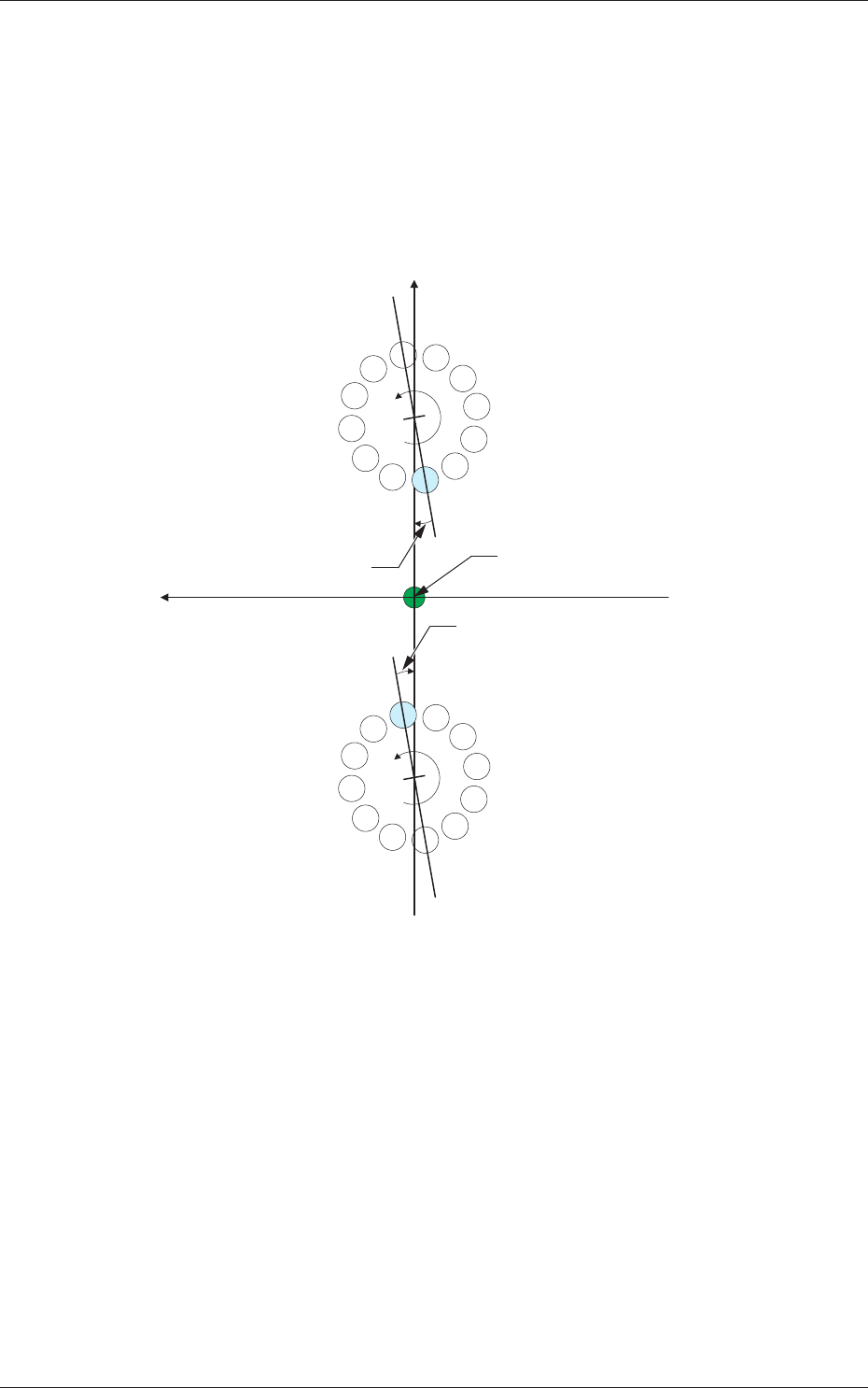
Head 1 and Head 2
Z [deg]
The set parameters are used to adjust the angular deviations of the line
connecting Nozzles 1 and 7 at the head rotational Z-phase position
based on the machine coordinate reference.
When the line is tilted clockwise in the machine reference X/Y
coordinate system, a plus sign must be affi xed to the offset data.
Xm (+)
Ym (+)
Xm-Ym : Machine Reference
Coordinate System
1
2
3
4
5
6
7
8
9
10
11
12
1
2
3
4
5
6
7
8
9
10
11
12
DD Motor Z-Phase
Stop Position
DD Motor Z-Phase
Stop Position
DD (+)
DD (+)
Head Rotational Angle Offset
Head Rotational Angle Offset
Pm. Machine Reference
Coordinate Origin
Fig. 3F22
2.1 Device Offset Data