3OM-1345-006_w.pdf - 第284页
6-53 AKHEDT -ID 2.2.1 Auto Operation Setup When the "Auto Operation Setup" tab is pressed in the "Auto Operation" tab sheet, the following tab sheet appears. Fig. 3F43-1 "Auto Operation Setup&quo…
6-52
AKHEDT-ID
2.2 Auto Operation
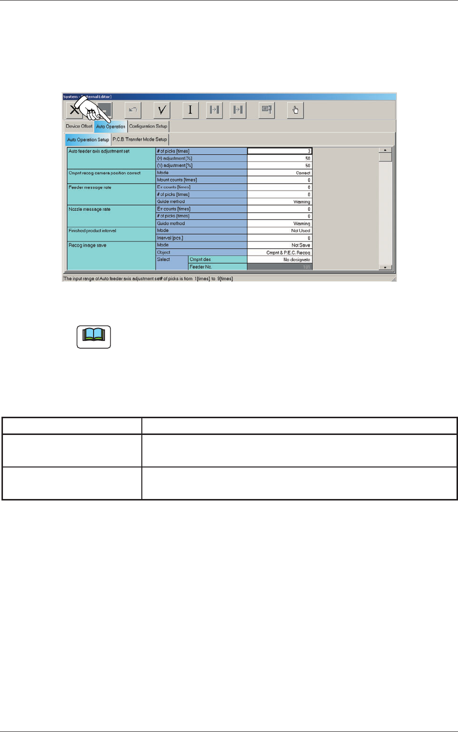
When the "Auto Operation" tab is pressed in the "System - [Internal Editor]"
window, the following tab sheet appears.
Fig. 3F42 "Auto Operation" Tab Sheet
Note
The tab sheet may look different, depending on which options are selected.
The "Auto Operation" tab sheet has the following subtab sheets. When a
subtab is pressed, the corresponding subtab sheet appears.
Table 3F4
Tabs Description
Auto Operation Setup
Set various types of parameters related to the automatic operation of
the machine.
PCB Transfer Mode Setup
Set the operation mode of the input and output machines and the
requirements for PCB transfer and positioning operations.
0605-002
2.2 Auto Operation
6-53
AKHEDT-ID
2.2.1 Auto Operation Setup
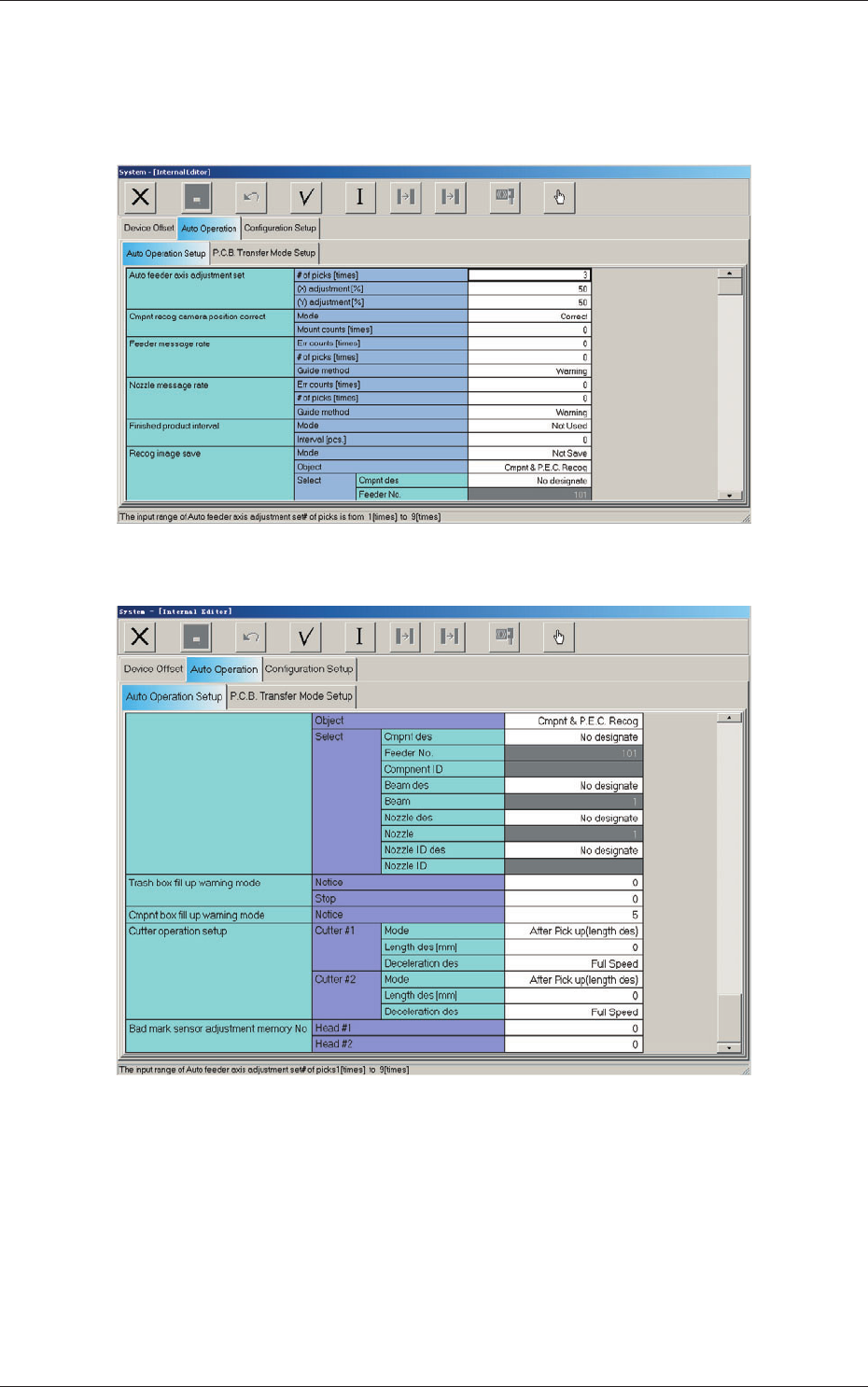
When the "Auto Operation Setup" tab is pressed in the "Auto Operation" tab
sheet, the following tab sheet appears.
Fig. 3F43-1 "Auto Operation Setup" Tab Sheet (1)
Fig. 3F43-2 "Auto Operation Setup" Tab Sheet (2)
2.2 Auto Operation
0605-002

6-54
AKHEDT-ID
[1] Auto feeder axis adjustment set
Set the sensitivity parameters which follow up the data learned by using
the statistical method in the feeder (B) offset data.
New Feeder (B) Offset
=
Old Feeder (B) Offset +
(Mean Value of "n" Times (Deviation))
×
Coeffi cient ((X) adjustment or (Y)
adjustment)
# of picks [times]
Set the total number of collected samples when data is updated or
changed.
(X) adjustment [%]
Select one of the following options as a feedback coeffi cient of the
mean of the X-direction deviation.
10, 20, 30, 40, 50, 60, 70, 80, 90, Full
(Y) adjustment [%]
Select one of the following options as a feedback coeffi cient of the
mean of the Y-direction deviation.
10, 20, 30, 40, 50, 60, 70, 80, 90, Full
[2] Cmpnt recog camera position correct
Mode
"Correct" or "No Correct" can be selected to determine whether or
not the component recognition camera position should be corrected
periodically.
Note
It is recommended to set "Correct" in normal cases.
Mount counts [times]
Press the icon (
) to open the "Ten-Key Pad" window and enter
either "0" or "1 to 9999".
0 :
No automatic correction operation is performed for
each number of components to be placed.
1 to 9999 :
Correction is made according to the specifi ed number
of components to be placed.
0602-001
2.2 Auto Operation