Specification SIPLACE CA-Series2014版.pdf - 第10页
10 Machine Description Technical Data - SWS T echnical Data Flip Chip Die Att ach Minimum die thickness (silici um) - without com- ponent sensor 50 µm 50 µm Minimum die thickness (silicium) - with compo- nent sensor 100 …

9
Machine Description
Technical Data - SMT
Number of gan-
tries
CA4: 4 gantries
Component feed-
ing
– SIPLACE CA4: Up to four SWS possible in placement area 1 and 2
– Component trolley (X-Series)
(with tape reel mount and integrated waste tape bin,
40 locations à 8 mm X feeder module per component trolley)
– Matrix Tray Changer (on request)
Feeder module
types
– X-Series component trolley: Tapes, waffle pack trays
Supply capacity
(X-Series compo-
nent trolley)
160 tracks Width: 10.8 mm 4 mm X feeder modules
160 tracks Width: 10.8 mm 8 mm X feeder modules
160 tracks Width: 22.9 mm Smart Feeder 2x8 mm X
80 tracks Width: 22.6 mm Smart Feeder 12 mm X
52 tracks Width: 22.6 mm Smart Feeder 16 mm X
52 tracks Width: 34.4 mm 24 mm X feeder modules
40 tracks Width: 46.2 mm 32 mm X feeder modules
32 tracks Width: 58.0 mm 44 mm X feeder modules
24 tracks Width: 69.8 mm 56 mm X feeder modules
20 tracks Width 81.6 mm 72 mm X feeder modules
16 tracks Width: 105.2 mm 88 mm X feeder modules

10
Machine Description
Technical Data - SWS
Technical Data Flip Chip Die Attach
Minimum die thickness (silicium) - without com-
ponent sensor
50 µm 50 µm
Minimum die thickness (silicium) - with compo-
nent sensor
100 µm 100 µm
Minimum bump size 50 µm n/a
Minimum bump grid 100 µm n/a
SIPLACE Wafer System SWS Horizontal system, automatic wafer change, MCM
SWS wafer size 4" to 12"
4" / 6" with adapter on request
Wafer frame 12“/8“
6" on request
4" with adapter
Hoop /grip ring thickness Max. 3.5 mm
Wafer magazine
a
a) Depending on the wafer magazine, you may need to mechanically adjust the base plate for the wafer magazines.
Up to 12"
Die Ejection System Programmable ejection speed (synchronous and asynchronous)
Option: Linear Dipping Unit LDU Individually programmable speed
Flux viscosity 3,000 to 100,000 cPs
Accuracy of flux height ± 5 µm
11
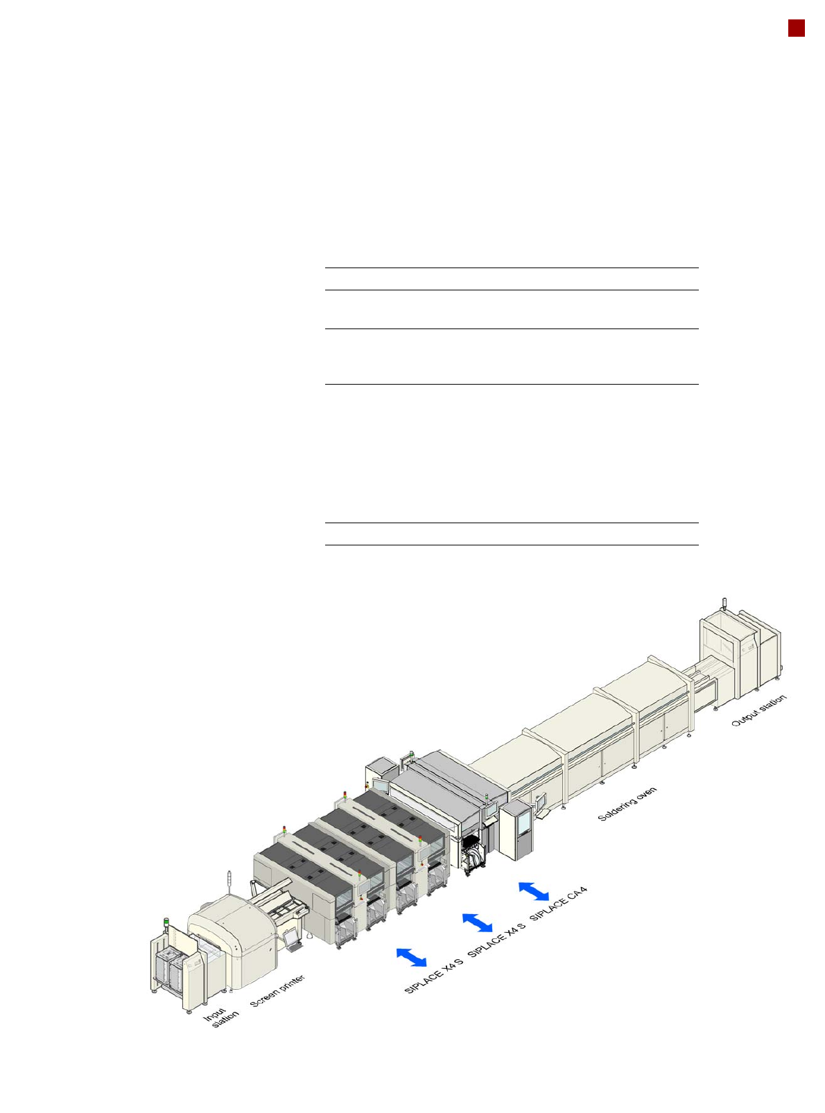
Line Concept
Description
The SIPLACE concept is dis-
tinguished by its flexibility,
modularity, compact design
and high performance. It al-
lows a production line to be
individually configured from
identical and different mod-
ules. If the production re-
quirements change, the indi-
vidual placement machines
are so compact that they can
be recombined quickly and
easily.
Operated together with the
SIPLACE X series, the SI-
PLACE CA machine allows
you to individually configure
your production line with both
identical and differing mod-
ules. If the production re-
quirements change, the indi-
vidual placement machines
are so compact and can be
combined with such flexibility
that they can be recombined
quickly and easily.
The SIPLACE CA family has
the optimum placement sys-
tem for each individual per-
formance requirement.
System SIPLACE Placement lines
Placement
module
SIPLACE CA4, SIPLACE X-Series,
SIPLACE SX1/SX2, SX4
Peripheral
modules
Input/output stations, screen printer, sol-
dering furnace, inspection places etc.
available from SIPLACE
PCB conveyor Single and dual conveyor with auto-
matic width adjustment unit;
Dual conveyor in single conveyor mode
"Wide board" mode with "long board"
option and a combination of these for
both PCB conveyors. The maximum
PCB width is determined by the module
with the smallest PCB conveyor width.
Space required 6.7 m² per CA4 module