Galaxy EX ProFlow Module.pdf - 第2页
PROFLOW M ODULE OVERVI EW 11. 2 Te chni cal Ref ere nce Ma nual Ch apte r Issue 4 , Jun 18 The P roFl ow m ech ani sm is dri ven ba ck ward s a nd for w ards a cros s the sc ree n by the pr int carr iag e ap plyin g pri …
PROFLOW MODULE
OVERVIEW
Chapter Issue 4, Jun 18 Technical Reference Manual 11.1
CHAPTER 11 PROFLOW MODULE
OVERVIEW
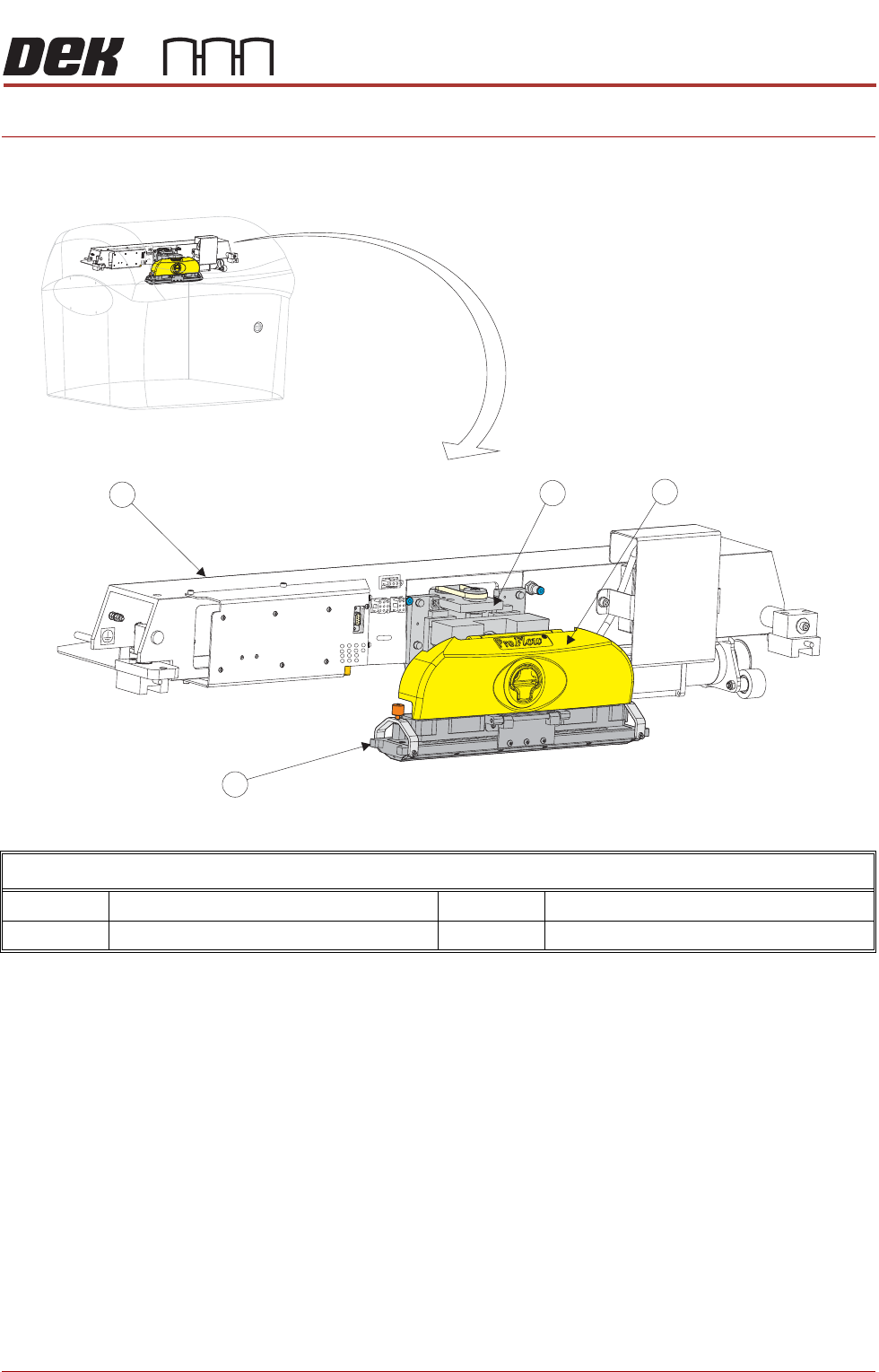
ProFlow Overview
1 ProFlow Printhead Mechanism 3 ProFlow Transfer Head
2 ProFlow Pressure Mechanism 4 Print Carriage
PROFLOW MODULE
OVERVIEW
11.2 Technical Reference Manual Chapter Issue 4, Jun 18
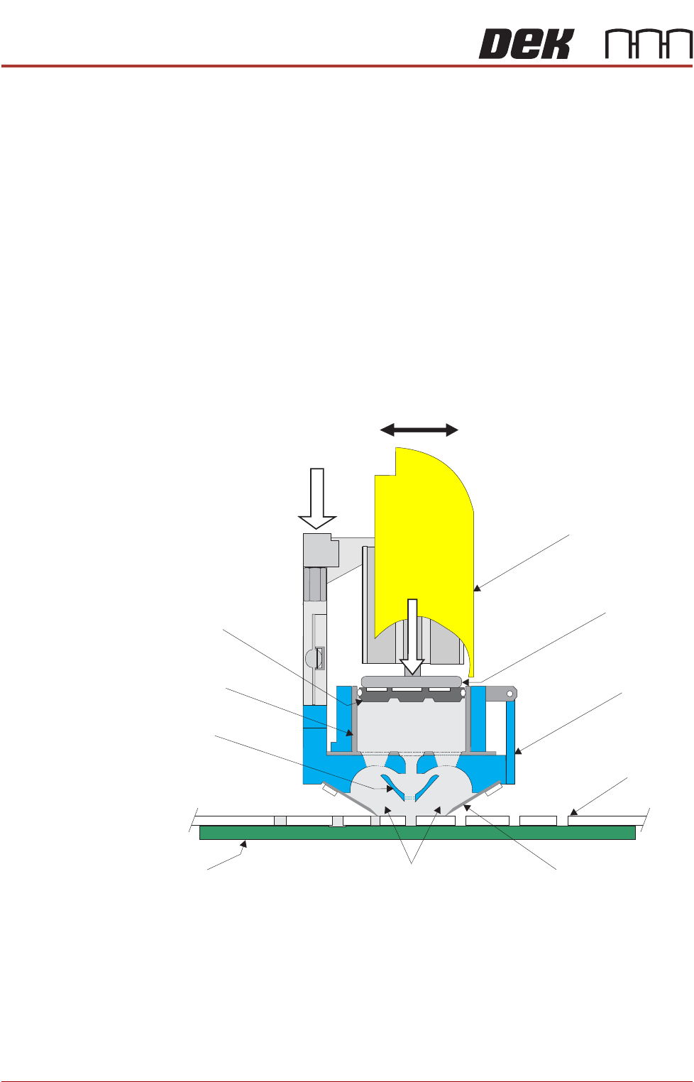
The ProFlow mechanism is driven backwards and forwards across the screen
by the print carriage applying printable material directly onto the screen. This
alleviates the need for squeegees and a paste dispenser.
The ProFlow mechanism is raised and lowered, to the screen by means of a
stepper motor, applying a downward force directly onto the screen providing a
positive seal between the transfer head and screen. This eliminates leakage of
print material above the screen.
Paste pressure (pneumatic), is applied to the piston crosshead exerting a
force onto the print material which, in turn, forces print material into the
ProFlow conditioning chamber and into the screen apertures.
As the unit moves across the screen the trailing wiper, within the transfer head,
lifts the print material from the screen surface, clearing the screen of print
material. In addition, the trailing wiper creates a rolling movement of material
within the conditioning chamber.
Figure 11-7 ProFlow Cross Section (with cassette option)
ProFlow Pressure
Mechanism
Transfer
Head
Stencil
Board
ProFlow M ovem ent (YAxis)
Wiper
Piston
Crosshead
Pneum atic
P ressure
S ystem Pressure
Print Material
Side Chambers
Cassette
Nozzle
Cassette
Plunger
PROFLOW MODULE
OVERVIEW
Chapter Issue 4, Jun 18 Technical Reference Manual 11.3
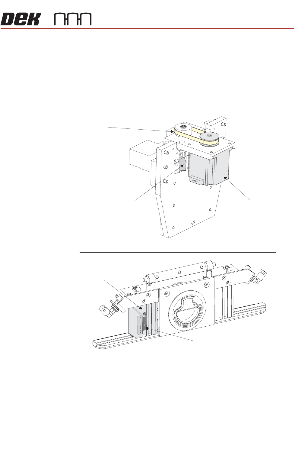
The sensor used to detect paste may be one of two types:
• ProFlow Cassette Low Sensor - Reed Switch (warns the operator when
the paste reaches a certain level)
• ProFlow Paste Level Sensor - Giant Magneto resistive (displays to the
operator a percentage of paste remaining (time-to-go))
In both cases the sensor is fitted to the left hand side pressure mechanism
pneumatic actuator, as shown in the figure below.
Figure 11-8 ProFlow Sensor and Stepper Motor Locations
View on R ear of ProFlow Printhead M echanism
ProFlow Home Sensor
Drive Belt
Stepper Motor
View on Front of ProFlow P ressure M echanism (cover rem oved)
Pneumatic Actuator
15
0
30
Paste Level Sensor
or
Cassette Low Sensor