Galaxy EX ProFlow Module.pdf - 第8页
PROFLOW M ODULE ADJUSTMENTS AND SETTINGS 11. 8 Te chni cal Ref ere nce Ma nual Ch apte r Issue 4 , Jun 18 Heigh t Adjustment T o se t the P roFlow HVM suppor t tool i ng to the corr ect heig h t carry out t he follo wing…
PROFLOW MODULE
ADJUSTMENTS AND SETTINGS
Chapter Issue 4, Jun 18 Technical Reference Manual 11.7
Rechargeable
Transfer Head
Option
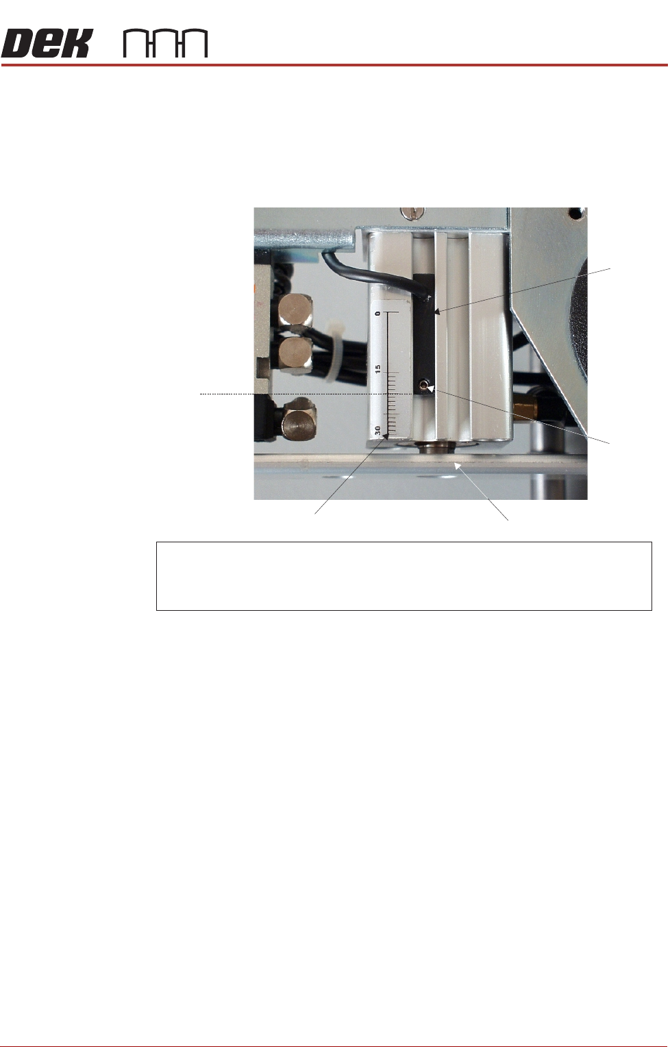
9. When using a rechargeable transfer head and ProFlow cassette low sen-
sor activation is required at the mid diaphragm point the reed sensor can
be inverted so that a higher sensor initiation can be achieved. (In this posi-
tion the sensor cable is at the bottom of the sensor.)
Figure 11-9 Cassette Low Sensor Adjustment
ProFlow HVM
Support Tooling
The ProFlow HVM support tooling provides support for stencils and hence the
ProFlow transfer head during printing. The use of the tooling avoids potential
print medium smearing onto the top of the stencil and stabilises the pressure
within the transfer head.
The height of the tooling is adjustable on the tooling base and is set to
approximately 75mm (Rail to Table Height). Each set of tooling is matched to
individual machines. The tooling base is identified by the machine serial
number written on the top face of the base once it has been calibrated to the
machine. The tooling comprises the following items:
• Adjustable tooling base
• Interchangeable tooling top
NOTE
Refer to Board Support Tooling chapter of this manual for further information.
NOTE
For ProFlow cassette option - ensure that the cable of the sensor is configured to the top.
R echargeable transfer head option - sensor may be inverted (cable to the bottom ) if
paste low activation is required at mid way point.
Securing
Screw
Graduated Scale (1mm increments)
Piston Crosshead
Sensor
20 mm
Factory Setting
PROFLOW MODULE
ADJUSTMENTS AND SETTINGS
11.8 Technical Reference Manual Chapter Issue 4, Jun 18
Height Adjustment To set the ProFlow HVM support tooling to the correct height carry out the
following:
NOTE
1. Ensure the machine is configured as a carrier handling option.
2. Ensure the Rail to Table Height is set to 75mm. If not, carry out the Chase
To Rail Parallelism (Carrier Handling Option) procedure in the Rising Table
Module.
1. From the Ready page, select Product Changeover.
2. Select Load Product.
3. Highlight a relevant product file for J-boat carriers and select Load.
4. Select Back.
5. Select Setup Tooling.
6. Select Full Width.
7. Select Open Cover Commands.
8. Open the front printhead cover.
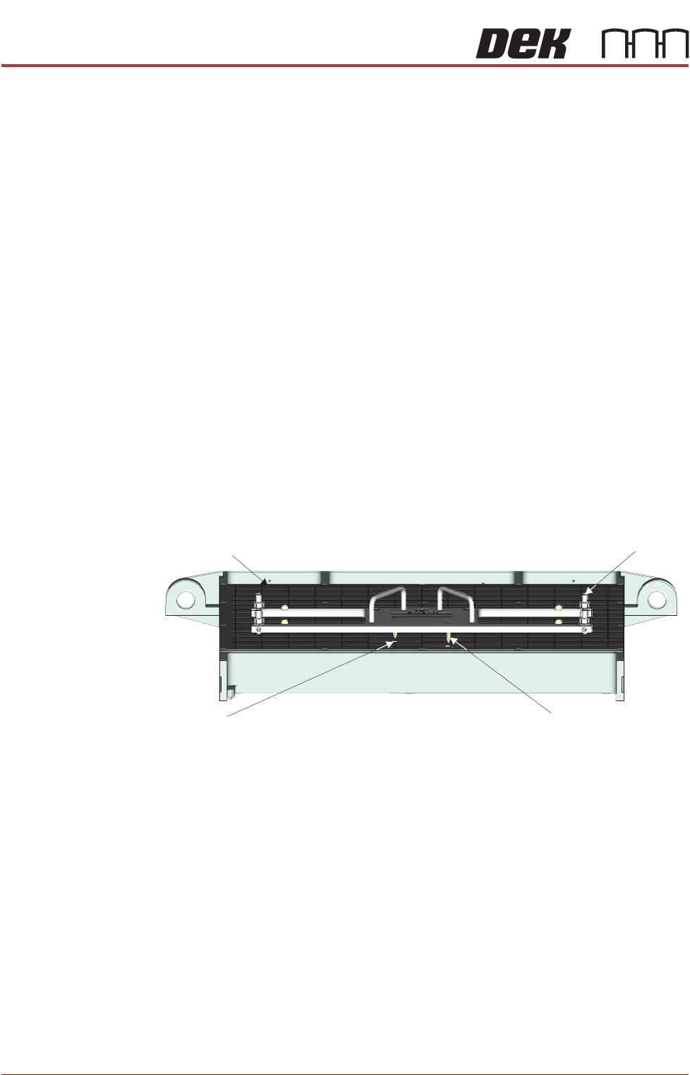
9. Using the two tooling base dowel pins, correctly locate and fit the HVM
tooling base to the manual tooling plate.
Manual Tooling Plate
Tooling Base
Tooling Base
Dowel Pin (in 2 Positions)
Tooling Plate Dowel
Hole (in 2 Positions)
Front View on M anual Tooling Plate
PROFLOW MODULE
ADJUSTMENTS AND SETTINGS
Chapter Issue 4, Jun 18 Technical Reference Manual 11.9
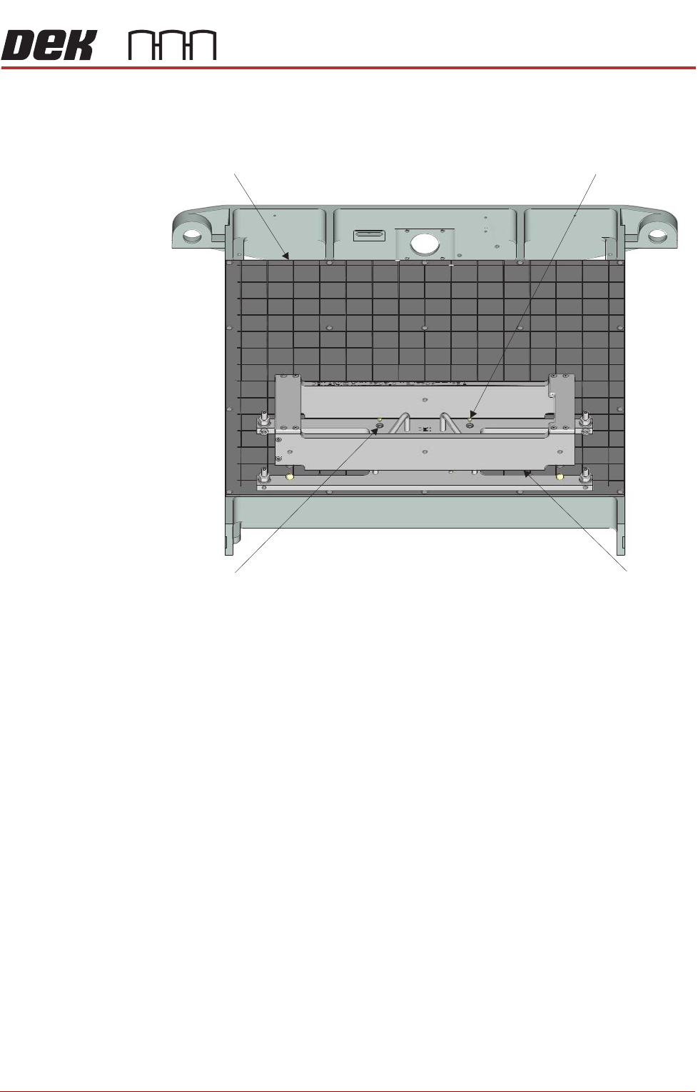
10. Place the tooling top onto the tooling base, ensuring the tooling top dowel
pins are correctly located in the top of the tooling base.
11. Close the front printhead cover.
12. Press the System button.
13. Select Back.
14. Select Board Width.
15. Select Transport Height.
16. Place an empty known good flat carrier on the input conveyor.
17. Select Load Board, the carrier is driven into the board stop position.
18. Select Vision Height.
19. Select Print Height.
20. Select Open Cover Commands.
21. Open the front printhead cover.
Manual Tooling Plate
Tooling Top
Tooling Top
Dowel Pin (in 2 Positions)
Tooling Base Dowel
Hole (in 2 Positions)
Front View on M anual Tooling Plate