Galaxy EX ProFlow Module.pdf - 第7页
PR O FLO W MO DU LE ADJUSTMENT S AND SETTINGS Ch apte r Issue 4, J un 18 Tech nical Ref erenc e Ma nual 11.7 Re cha rge abl e T ransfe r Head Opt ion 9. W he n usin g a re cha rge ab le tran sfe r he ad and Pro F low cas…
PROFLOW MODULE
ADJUSTMENTS AND SETTINGS
11.6 Technical Reference Manual Chapter Issue 4, Jun 18
ADJUSTMENTS AND SETTINGS
ProFlow Paste
Level Sensor
There is no adjustment and setting for this sensor.
ProFlow Cassette
Low Sensor
The ProFlow cassette low sensor position can be changed in order to minimize
print material wastage. A graduated scale (millimetre) on the actuator cylinder
body provides a reference point for accurate sensor positioning, (Cassette
Low Sensor Adjustment figure refers). The sensor is moved up or down by
loosening the securing screw, (1.5mm Allen key).
The factory setting for the sensor is set to 20mm on the graduated scale. Each
millimetre movement is equivalent to approximately 43gms of print material
usage.
CAUTION
SOLDER PASTE AND SOLVENTS. WHEN USING OR HANDLING ANY SOLDER
PASTE OR SOLVENT FORMULATION THE MANUFACTURERS’ SAFETY DATA
SHEETS MUST BE STRICTLY ADHERED TO.
The following procedure should be carried out when print material wastage is
excessive.
1. Gain access to the ProFlow unit by opening the printhead cover.
2. Lift off the ProFlow pressure mechanism cover.
3. Confirm that a ProFlow cassette low sensor is fitted and not a ProFlow
paste level sensor. If a ProFlow paste level sensor is fitted do not continue
with this procedure.
NOTE
A ProFlow paste level sensor has a ribbon cable.
Cassette Option 4. Noting the present position of the sensor against the graduated marker,
loosen the sensor using a 1.5mm Allen key.
5. With each 1mm graduation on the scale being equivalent to approximately
43gms of print material, move the sensor down by single graduations until
the optimum print material usage position is obtained, (Cassette Low Sen-
sor Adjustment Figure refers).
6. Carefully re-tighten the sensor securing screw.
NOTE
To prevent damage to the sensor, do not overtighten grub screw.
7. Replace the pressure mechanism cover.
8. Close the front printhead cover.
PROFLOW MODULE
ADJUSTMENTS AND SETTINGS
Chapter Issue 4, Jun 18 Technical Reference Manual 11.7
Rechargeable
Transfer Head
Option
9. When using a rechargeable transfer head and ProFlow cassette low sen-
sor activation is required at the mid diaphragm point the reed sensor can
be inverted so that a higher sensor initiation can be achieved. (In this posi-
tion the sensor cable is at the bottom of the sensor.)
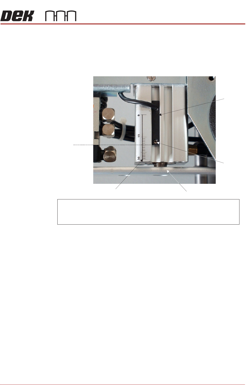
Figure 11-9 Cassette Low Sensor Adjustment
ProFlow HVM
Support Tooling
The ProFlow HVM support tooling provides support for stencils and hence the
ProFlow transfer head during printing. The use of the tooling avoids potential
print medium smearing onto the top of the stencil and stabilises the pressure
within the transfer head.
The height of the tooling is adjustable on the tooling base and is set to
approximately 75mm (Rail to Table Height). Each set of tooling is matched to
individual machines. The tooling base is identified by the machine serial
number written on the top face of the base once it has been calibrated to the
machine. The tooling comprises the following items:
• Adjustable tooling base
• Interchangeable tooling top
NOTE
Refer to Board Support Tooling chapter of this manual for further information.
NOTE
For ProFlow cassette option - ensure that the cable of the sensor is configured to the top.
R echargeable transfer head option - sensor may be inverted (cable to the bottom ) if
paste low activation is required at mid way point.
Securing
Screw
Graduated Scale (1mm increments)
Piston Crosshead
Sensor
20 mm
Factory Setting
PROFLOW MODULE
ADJUSTMENTS AND SETTINGS
11.8 Technical Reference Manual Chapter Issue 4, Jun 18
Height Adjustment To set the ProFlow HVM support tooling to the correct height carry out the
following:
NOTE
1. Ensure the machine is configured as a carrier handling option.
2. Ensure the Rail to Table Height is set to 75mm. If not, carry out the Chase
To Rail Parallelism (Carrier Handling Option) procedure in the Rising Table
Module.
1. From the Ready page, select Product Changeover.
2. Select Load Product.
3. Highlight a relevant product file for J-boat carriers and select Load.
4. Select Back.
5. Select Setup Tooling.
6. Select Full Width.
7. Select Open Cover Commands.
8. Open the front printhead cover.
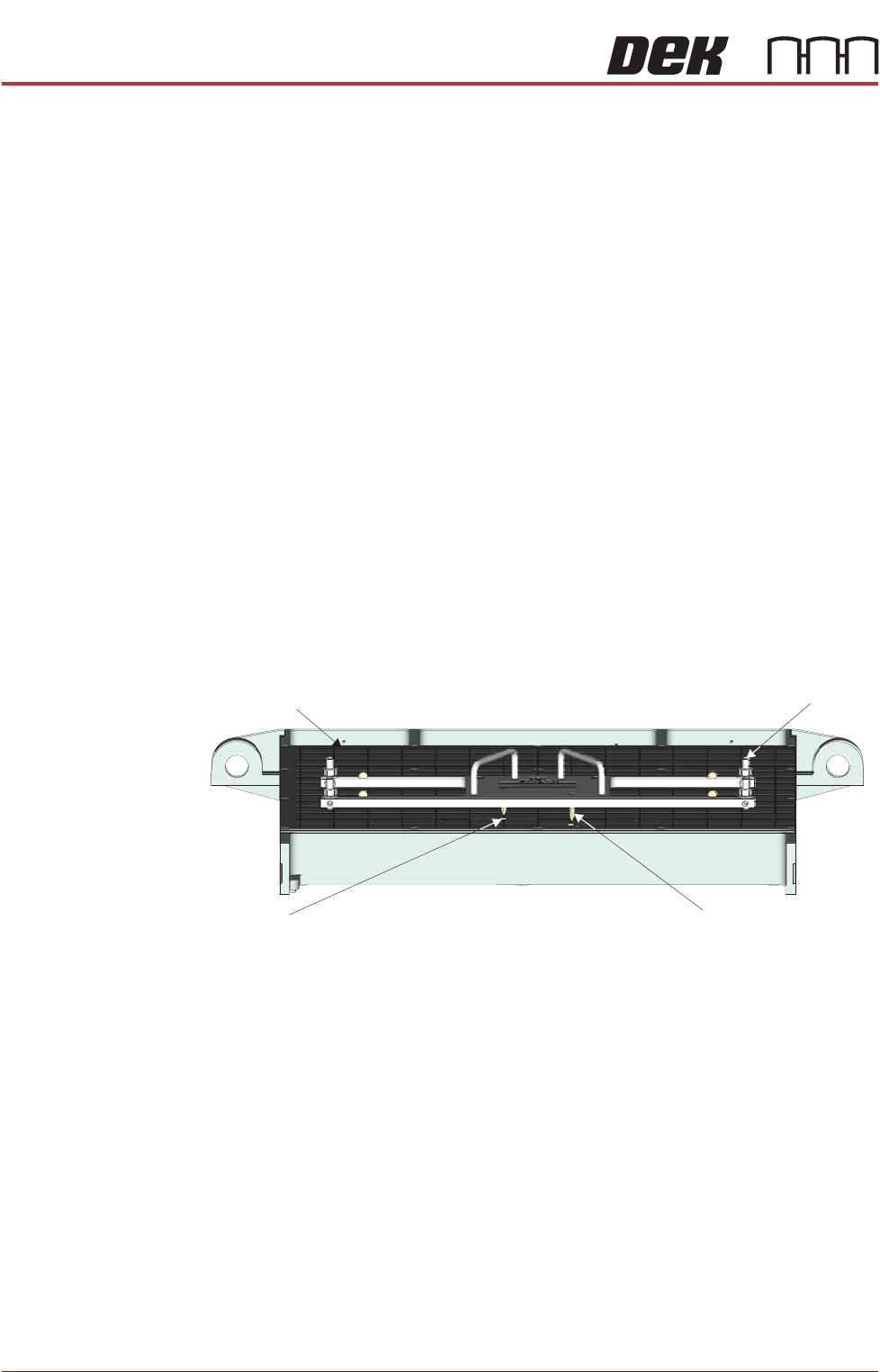
9. Using the two tooling base dowel pins, correctly locate and fit the HVM
tooling base to the manual tooling plate.
Manual Tooling Plate
Tooling Base
Tooling Base
Dowel Pin (in 2 Positions)
Tooling Plate Dowel
Hole (in 2 Positions)
Front View on M anual Tooling Plate