Galaxy EX ProFlow Module.pdf - 第4页
PROFLOW M ODULE OVERVI EW 11. 4 Te chni cal Ref ere nce Ma nual Ch apte r Issue 4 , Jun 18 The follow i ng co nfigu ratio ns of Pr oFlo w are av aila ble fo r use on t he ma chin e: Ca sset te Th e Pr oFl ow c as set te …
PROFLOW MODULE
OVERVIEW
Chapter Issue 4, Jun 18 Technical Reference Manual 11.3
The sensor used to detect paste may be one of two types:
• ProFlow Cassette Low Sensor - Reed Switch (warns the operator when
the paste reaches a certain level)
• ProFlow Paste Level Sensor - Giant Magneto resistive (displays to the
operator a percentage of paste remaining (time-to-go))
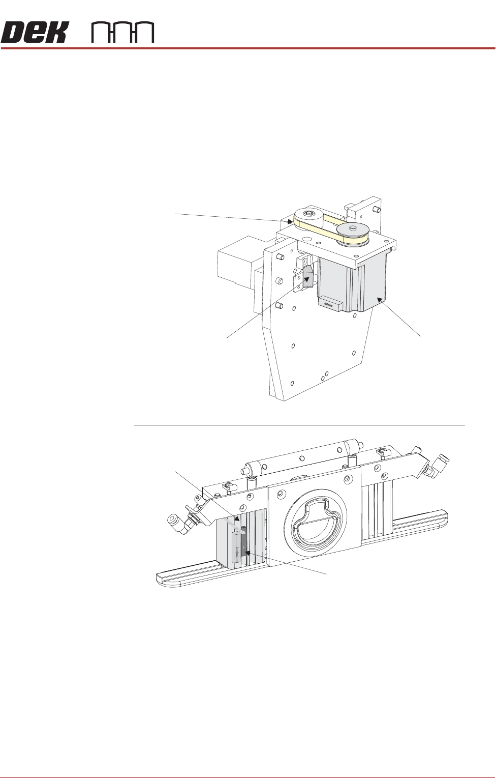
In both cases the sensor is fitted to the left hand side pressure mechanism
pneumatic actuator, as shown in the figure below.
Figure 11-8 ProFlow Sensor and Stepper Motor Locations
View on R ear of ProFlow Printhead M echanism
ProFlow Home Sensor
Drive Belt
Stepper Motor
View on Front of ProFlow P ressure M echanism (cover rem oved)
Pneumatic Actuator
15
0
30
Paste Level Sensor
or
Cassette Low Sensor
PROFLOW MODULE
OVERVIEW
11.4 Technical Reference Manual Chapter Issue 4, Jun 18
The following configurations of ProFlow are available for use on the machine:
Cassette The ProFlow cassette is available in 300mm size only (capacity approximately
800g - 850g solder paste).
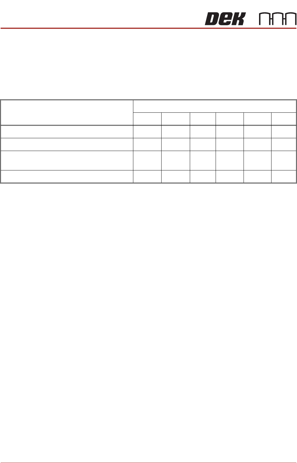
Transfer Head The table below lists the types of optional transfer head units and sizes
available, for use with ProFlow:
NOTE
All of the above cassette transfer heads are fitted with the standard 300mm
cassette and 300mm piston crosshead. A dedicated piston crosshead is
required for each rechargeable transfer head size.
Transfer Head Type
Transfer Head Sizes (mm)
150 300 350 400 450 500
Cassette Type (single conditioning chamber)
Yes Yes Yes
Cassette Type (dual conditioning chamber)
Yes Yes Yes
Rechargeable Type (single conditioning
chamber)
Yes Yes Yes Yes Yes
Rechargeable Type (dual conditioning chamber)
Yes Yes Yes Yes Yes Yes
PROFLOW MODULE
ELECTRICAL SCHEMATIC
Chapter Issue 4, Jun 18 Technical Reference Manual 11.5
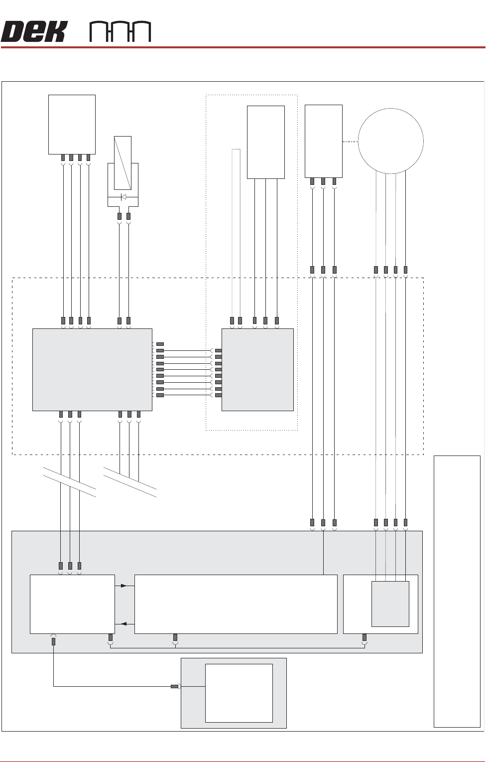
ELECTRICAL SCHEMATIC
ProFlow
Fitted Link
Motor 2 B-
Motor 2 B+
Motor 2 A-
Motor 2 A+
Print Carriage
9PL08
9PL17
Print Carriage I/O
Node 3
N3PL13
N3PL17
N3PL8
M36PL35
N3SK2
N3SK3
CAN Bus
USB
NextMove ES
(I/O Node 1)
NextMove
Interface
Dual Stepper
Card X2
M36 Machine Control
PC
Motherboard
Step 4
M36PL12
M36PL21
CAN
Out
CAN
In
Stepper
Motor
(9M4)
ProFlow
Home
(9SE05)
+12V
0V
Signal
Pneumatic
Valve
(9S0L25)
+
-
+24V
Monitor O/P
I/P Signal
0V
ProFlow SCAR
M18SK02
+12V
0V
Signal
Paste
Level
(9SE25)
ProFlow Paste
Level Amplifier
1
9
9SK61
9PL62
ProFlow ‘Time To Go’
NOTE
The breaks in the CAN Bus chain reflect that additional I/O Nodes
may be fitted, refer to Machine Control chapter for the complete
CAN Bus chain.