Setup Center mit Setup Center Interface.pdf - 第11页
SIPLACE 3 Application program interface (API) description Ausgabe 05/2007 11 3 Application program interface (API) description 3.1 Overview The interface ‘ISetupCen ter ’ provides a public in terface to interact wi th SI…

2 Installation SIPLACE
Ausgabe 05/2007
10
2.2 Liste relevanter Begriffe und Abkürzungen
2
2
2
2
BE
Bauelement
BB
Bearbeitungsbereich
C&P
Collect & Place
DIPF
Device Independent Package Form
FFI
Flexible Feeder Interface (Flexible Förderer-Schnittstelle)
GUI
Graphical User Interface (Grafische Benutzeroberfläche)
HW
Hardware
LP
Leiterplatte
LM
Leistungsmerkmal
MC
Maschinencontroller
MTC
Matrix Tray Changer
OIS
Operator Information System
P&P
Pick & Place
PPW
Pipettenwechsler
RP
Recovery Placement
SMV
SIPLACE Mobile Verifier
SPL
SIPLACE Productivity Lift
SR
Stationsrechner
SW
Software
TH
Twinhead
VR
Vision-Rechner
WDTL
Whispering down the Line
WDTM
Whispering down the Machine
X2
Maschinentyp der X-Serie mit 2 Portalen
X3
Maschinentyp der X-Serie mit 3 Portalen
X4
Maschinentyp der X-Serie mit 4 Portalen
SIPLACE 3 Application program interface (API) description
Ausgabe 05/2007
11
3 Application program interface (API)
description
3.1 Overview
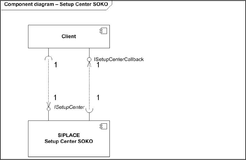
The interface ‘ISetupCenter’ provides a public interface to interact with SIPLACE Setup Center
(see Figure 1 – Overview). The interface will be implemented on the baseline of SIPLACE Setup
Center 2.2 SP 1 and bases on .NET Remoting Version 1.1. 3
The events which are provide by SIPLACE Setup Center can be get, if the client implements the
interface ‘ISetupCenterCallback’. The client publish the .NET Remoting interface and register it at
the Setup Center. 3
The interface description can be found in the component ‘sci.dll’, which is installed automatically
and saved in program folder of Setup Center. 3
3
Fig. 3.10 - 1 Overview
In this document all software diagrams based on UML 2.1. 3
3 Application program interface (API) description SIPLACE
Ausgabe 05/2007
12
3.2 SCI Interface
3.2.1 Data model
3.2.1.1 Overview
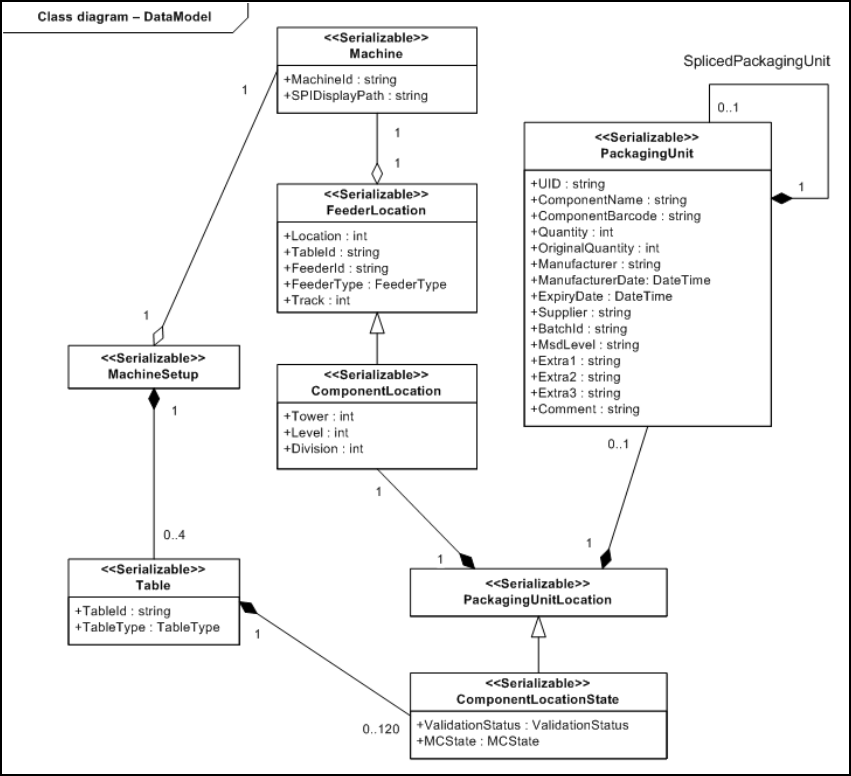
The following diagram describes all data classes and their relations. The classes are used by the
functions of the interfaces to exchange informations. 3
3
Fig. 3.11 - 1 Date model used by the interfaces
3
The detailed information for each class and its properties can be found in the following chapters.
Please, see below. 3
3