AG900+ and AG900+S Applicators Customer Product Manual.pdf - 第40页
AG − 900+ and AG900+S Applicators 36 Part 1098464A 2009 Nordson Corporation Body-Seal Replacement T o replace the body seal, perform the following procedure: 1. See Figure 24. Place a small amount of o-ring lubricant o…
AG−900+ and AG900+S Applicators
35
2009 Nordson Corporation
Part 1098464A
2
3
9
4
6
8
5
1
1
7
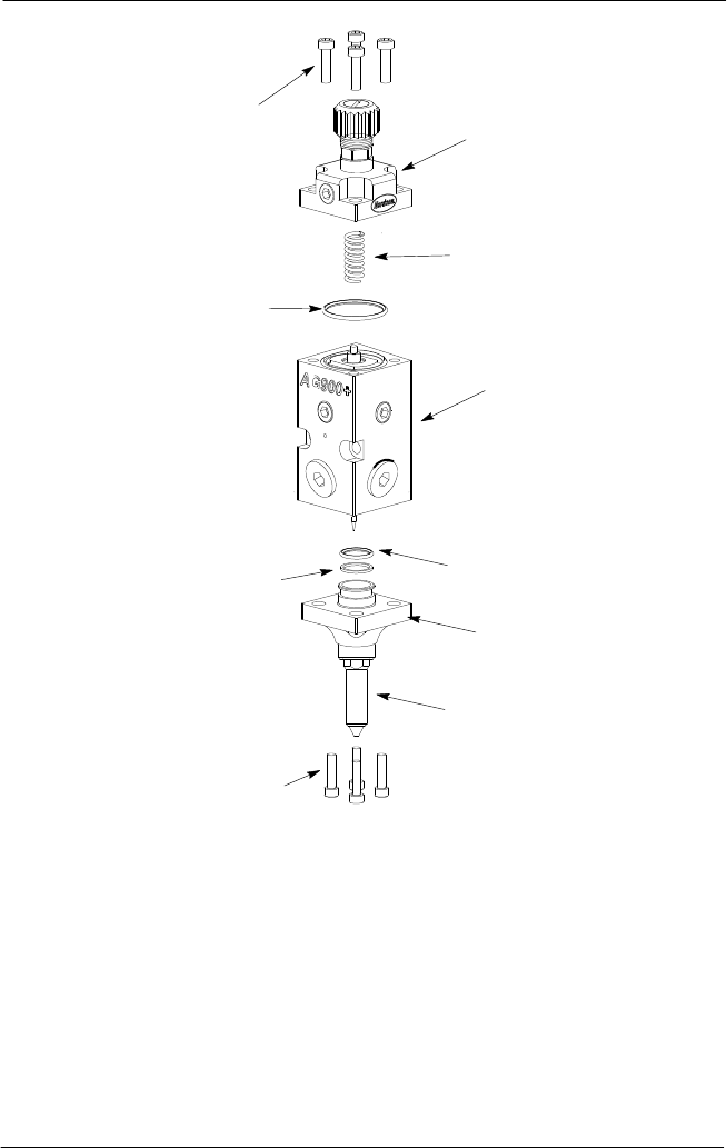
Figure 23: AG-900+/AG900+S Applicator Assembly
1. Socket head screws
2. Air cap
3. Spring
4. Applicator module body with piston/cartridge and
needle assemblies installed
5. O-ring
6. Nozzle flange
7. Nozzle
8. Back-up ring
9. Large o-ring (top of
piston/cartridge assembly)
AG−900+ and AG900+S Applicators
36
Part 1098464A
2009 Nordson Corporation
Body-Seal Replacement
To replace the body seal, perform the following procedure:
1. See Figure 24. Place a small amount of o-ring lubricant on new o-ring and install o-ring
in groove on back of module body.
2. Attach the applicator module to the regulator or applicator adapter body. Insert guide
pins into the mating holes for proper alignment.
3. Apply Never Seez lubricant to the two socket head mounting screws. Install the two
socket head mounting screws into the applicator body and tighten.
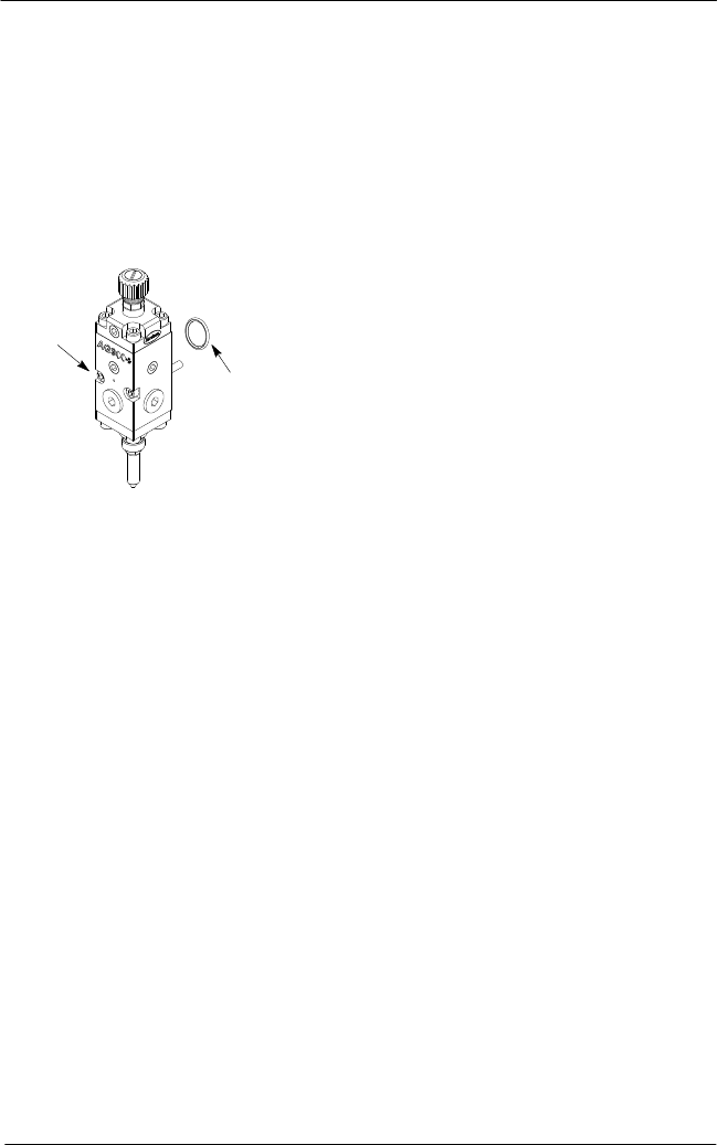
Figure 24: Applicator Body
1. Applicator module o-ring
2. Socket head mounting screws
1
2
AG−900+ and AG900+S Applicators
37
2009 Nordson Corporation
Part 1098464A
Regulator Spring Replacement
The following paragraphs provide procedures for spring replacement of the regulator.
Disassembly
To disassemble the regulator, perform the following procedure:
1. For heated applicators only, disconnect and lock out input electrical power from the
system. Unplug the regulator heater cordset and the hose connection cordset.
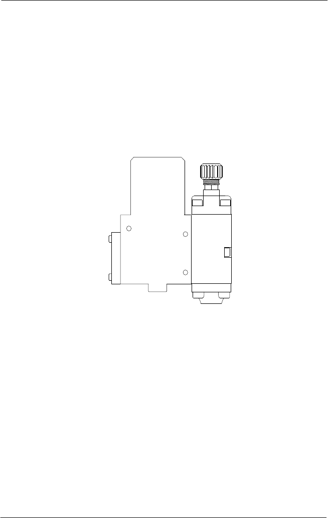
2. Relieve pressure to the applicator See Figure 25.. Disconnect the material supply hose
from the hose connection, then remove the three M5 socket head screws. Remove the
applicator assembly from the bracket.
Figure 25: AG-900+/AG900+S Applicator
3. Remove the two M5 socket head screws from the applicator body. Carefully remove the
applicator module from the regulator module.
NOTE: Perform this step to prevent damage to the nozzle/needle service kit during
regulator assembly.
4. See Figure 26. Unscrew and remove the regulator adjustment screw (1) from the
regulator body. Remove the spring seat (2), thrust bearing (4), and spring (3) from the
regulator piston bore.