AG900+ and AG900+S Applicators Customer Product Manual.pdf - 第44页
AG − 900+ and AG900+S Applicators 40 Part 1098464A 2009 Nordson Corporation Regulator Heater Cartridge Replacement (contd) 4 2 6 5 3 1 3 7 Figure 28: AG-900+/AG900+S Applicator Heater Assembly 1. Heater cartridge 2. He…
AG−900+ and AG900+S Applicators
39
2009 Nordson Corporation
Part 1098464A
Regulator Heater Cartridge Replacement
To replace the regulator heater cartridges, perform the following procedure:
1. Disconnect and lock out input electrical power from the applicator.
NOTE: Do not perform the following step unless the location of the applicator
assembly prohibits easy access to the heater cartridges and RTD.
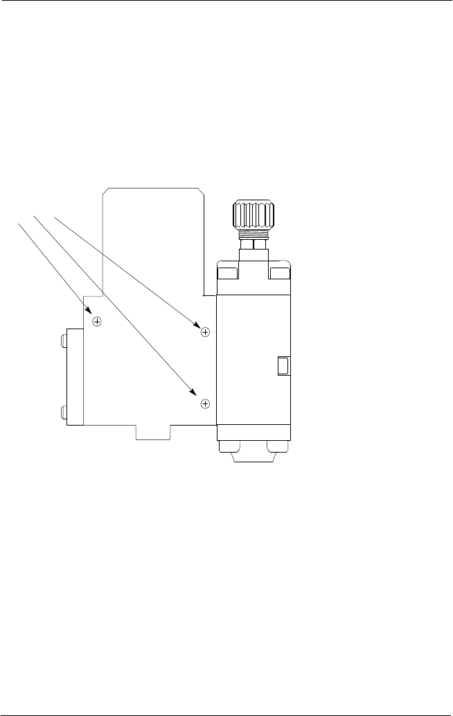
2. See Figure 27. Unplug the heater cordset from the hose or extension cable, remove the
three socket head screws, pull the applicator assembly away and separate the heater
assembly from the applicator.
M5 Screw
Figure 27: AG-900+/AG900+S Applicator
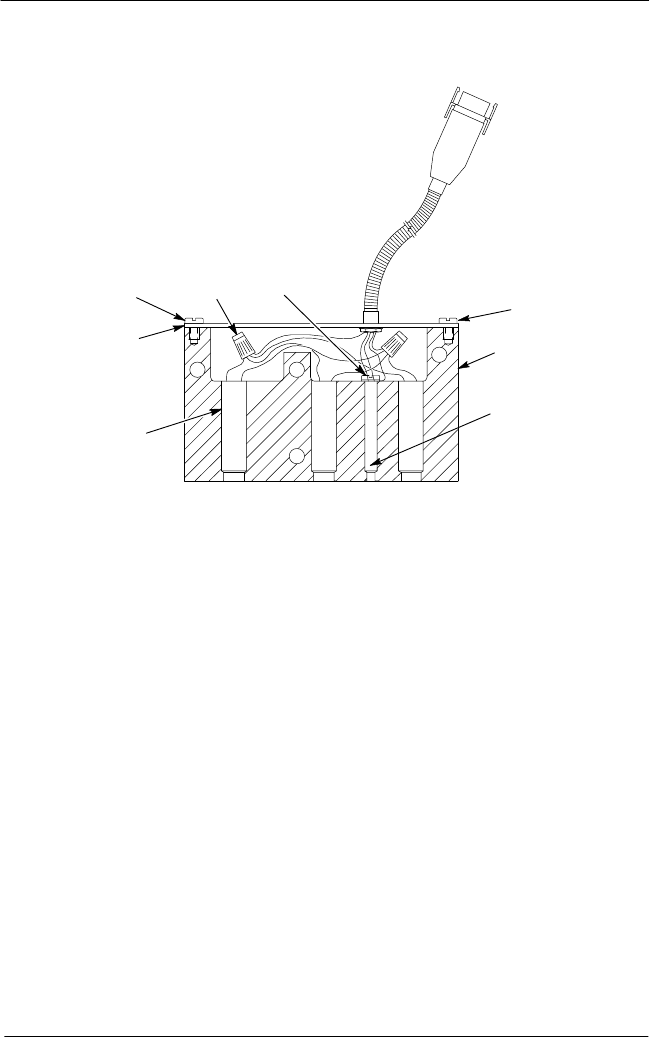
3. See Figure 28. Remove the two pan head screws (3) and the heated cover (2).
4. Remove the ground screw assembly (5).
NOTE: The heater cartridges are wired in parallel. Note their connections before
proceeding.
5. Remove the two porcelain wire connectors (4) that secure heater leads to the cordset
leads, separate the leads, and then pull the heater cartridges (1) from the heater body
(6).
AG−900+ and AG900+S Applicators
40
Part 1098464A
2009 Nordson Corporation
Regulator Heater Cartridge Replacement (contd)
4
2
6
5
3
1
3
7
Figure 28: AG-900+/AG900+S Applicator Heater Assembly
1. Heater cartridge
2. Heated cover
3. Pan head screw
4. Porcelain wire connector
5. Ground screw assembly
6. Heater body
7. RTD
6. Coat the new heater cartridges with thermal joint compound, then slide the heater
cartridges into the heater body.
7. Reconnect the heater cartridge leads in parallel as noted earlier, then reinstall the
porcelain wire connectors.
8. Secure the ground wire in place using the screw and lockwasher.
9. Apply Never Seez lubricant to the two pan head screws and use them to reinstall the
cover in place.
10. If the heater assembly was removed from the regulator, apply Never Seez lubricant
to the socket head screws, position the heater assembly against the regulator, position
the applicator assembly at the mounting bracket and reinstall the three socket head
screws.
11. Connect the regulator heater plug to the processor or extension cable and apply
input power.
AG−900+ and AG900+S Applicators
41
2009 Nordson Corporation
Part 1098464A
Using the Illustrated Parts Lists
To order parts, call the Nordson Customer Service Center or your local Nordson
representative. Use these five-column parts lists, and the accompanying illustrations, to
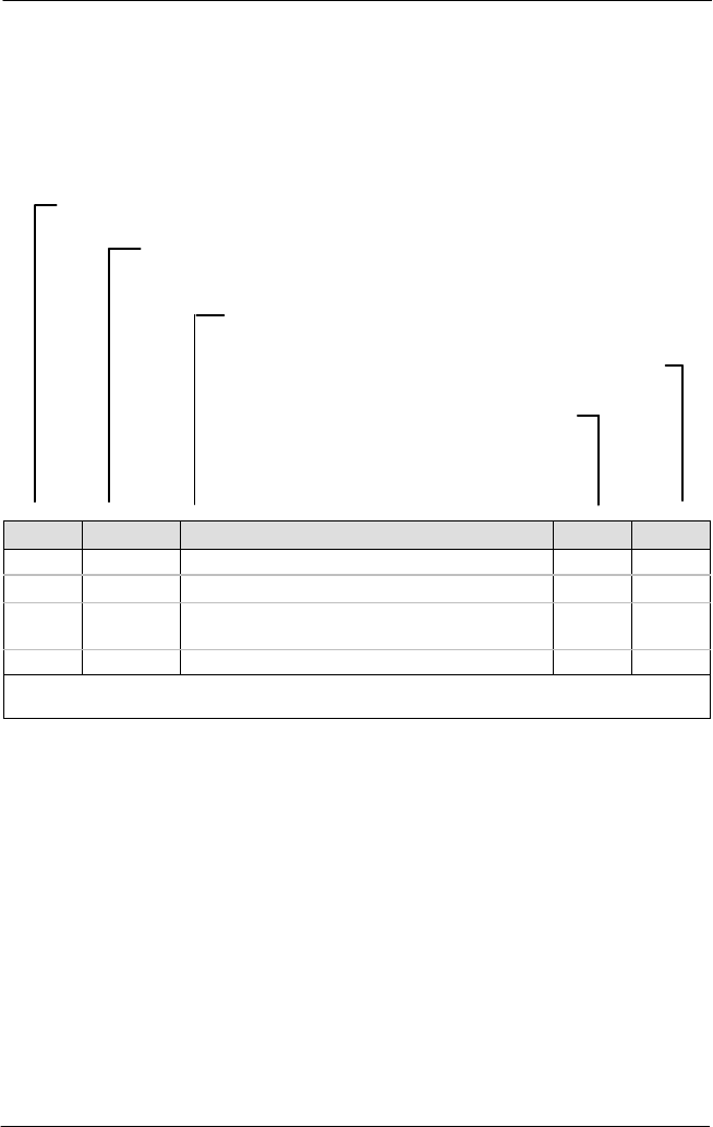
describe and locate parts correctly. The following chart provides guidance for reading the
parts lists.
The number in the Item column corresponds to the circled item number in the parts list
illustration. A dash in this column indicates that the item is an assembly.
The number in the Part column is the Nordson part number you can use to order the
part. A series of dashes indicates that the part is not saleable. In this case, you must
order either the assembly in which the part is used or a service kit that includes the part.
The Description column describes the part and sometimes includes
dimensions or specifications.
The Note column contains letters that refer to notes at the bottom of
the parts list. These notes provide important information about the
part.
The Quantity column tells you how many of the part
is used to manufacture the assembly shown in the
parts list illustration. A dash or AR in this column
indicates that the amount of the item required in the
assembly is not quantifiable.
Item Part Description Qty Note
– 0000000
Assembly A
–
1 000000
Part of assembly A
2 A
2 − − − − −
−
Part of item 1
1
NS 0000000
Part of item 2
NOTE A:
NS: Not Shown