AG900+ and AG900+S Applicators Customer Product Manual.pdf - 第42页
AG − 900+ and AG900+S Applicators 38 Part 1098464A 2009 Nordson Corporation Assembly T o assemble the AG-900+/AG900+S regulator , perform the following procedure: 5. Lubricate O-rings with Parker lubricant. 6. Lubricat…
AG−900+ and AG900+S Applicators
37
2009 Nordson Corporation
Part 1098464A
Regulator Spring Replacement
The following paragraphs provide procedures for spring replacement of the regulator.
Disassembly
To disassemble the regulator, perform the following procedure:
1. For heated applicators only, disconnect and lock out input electrical power from the
system. Unplug the regulator heater cordset and the hose connection cordset.
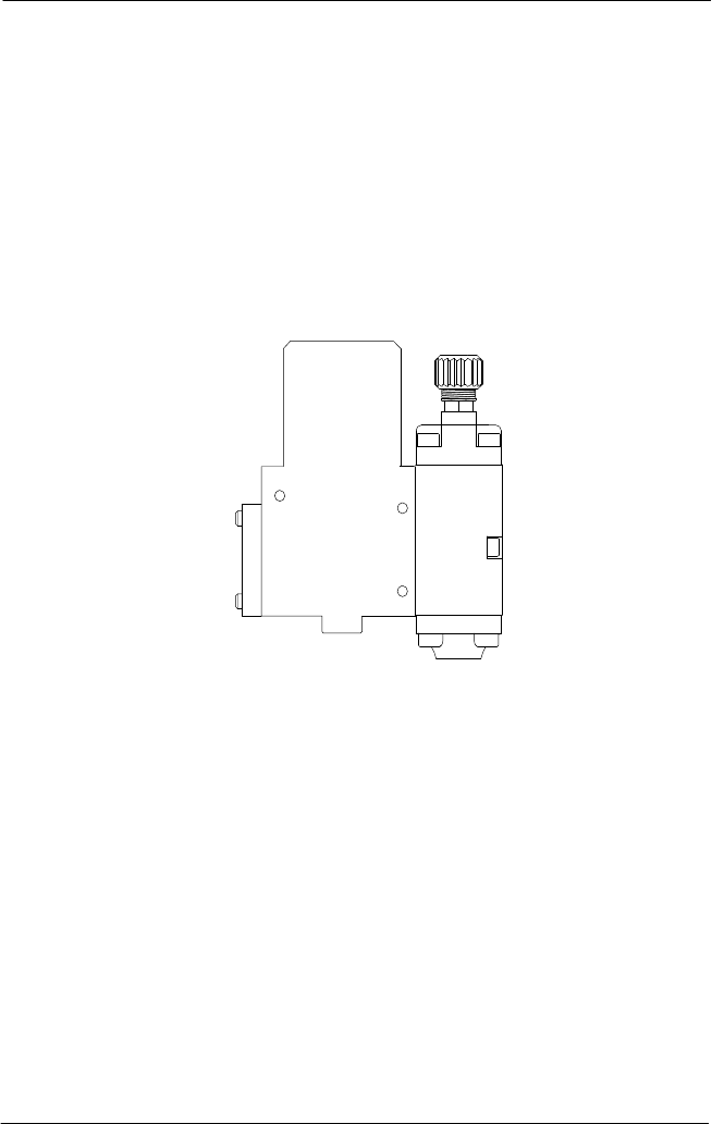
2. Relieve pressure to the applicator See Figure 25.. Disconnect the material supply hose
from the hose connection, then remove the three M5 socket head screws. Remove the
applicator assembly from the bracket.
Figure 25: AG-900+/AG900+S Applicator
3. Remove the two M5 socket head screws from the applicator body. Carefully remove the
applicator module from the regulator module.
NOTE: Perform this step to prevent damage to the nozzle/needle service kit during
regulator assembly.
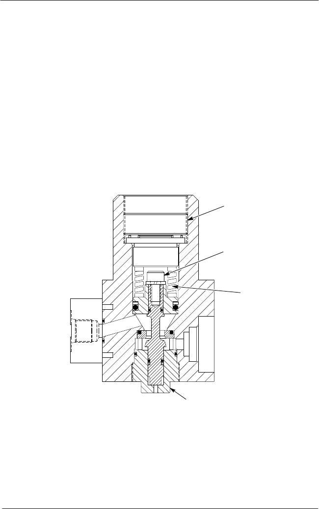
4. See Figure 26. Unscrew and remove the regulator adjustment screw (1) from the
regulator body. Remove the spring seat (2), thrust bearing (4), and spring (3) from the
regulator piston bore.
AG−900+ and AG900+S Applicators
38
Part 1098464A
2009 Nordson Corporation
Assembly
To assemble the AG-900+/AG900+S regulator, perform the following procedure:
5. Lubricate O-rings with Parker lubricant.
6. Lubricate the thrust bearing (4). Replace spring, spring seat, and thrust bearing into the
regulator body.
7. Lubricate the adjusting screw (1) with Never Seez lubricant and insert into regulator body.
8. Position the applicator body against the regulator and secure it in place with the two M5
socket head screw. Apply Never Seez lubricant to the screws before installing them.
9. Secure the applicator assembly to the bracket with the three M5 socket head screws.
Apply Never Seez lubricant to the screws before installing them. Reconnect the material
supply hose to the hose connection.
10. For heated applicators, reconnect the input electrical power to the applicator. Plug
in the regulator heater cordset and the hose connection cordset and resume normal
operation.
1
2
3
4
Figure 26: AG-900+/AG900+S Applicator Regulator Assembly
1. Regulator adjustment screw
2. Spring seat
3. Spring
4. Thrust bearing
AG−900+ and AG900+S Applicators
39
2009 Nordson Corporation
Part 1098464A
Regulator Heater Cartridge Replacement
To replace the regulator heater cartridges, perform the following procedure:
1. Disconnect and lock out input electrical power from the applicator.
NOTE: Do not perform the following step unless the location of the applicator
assembly prohibits easy access to the heater cartridges and RTD.
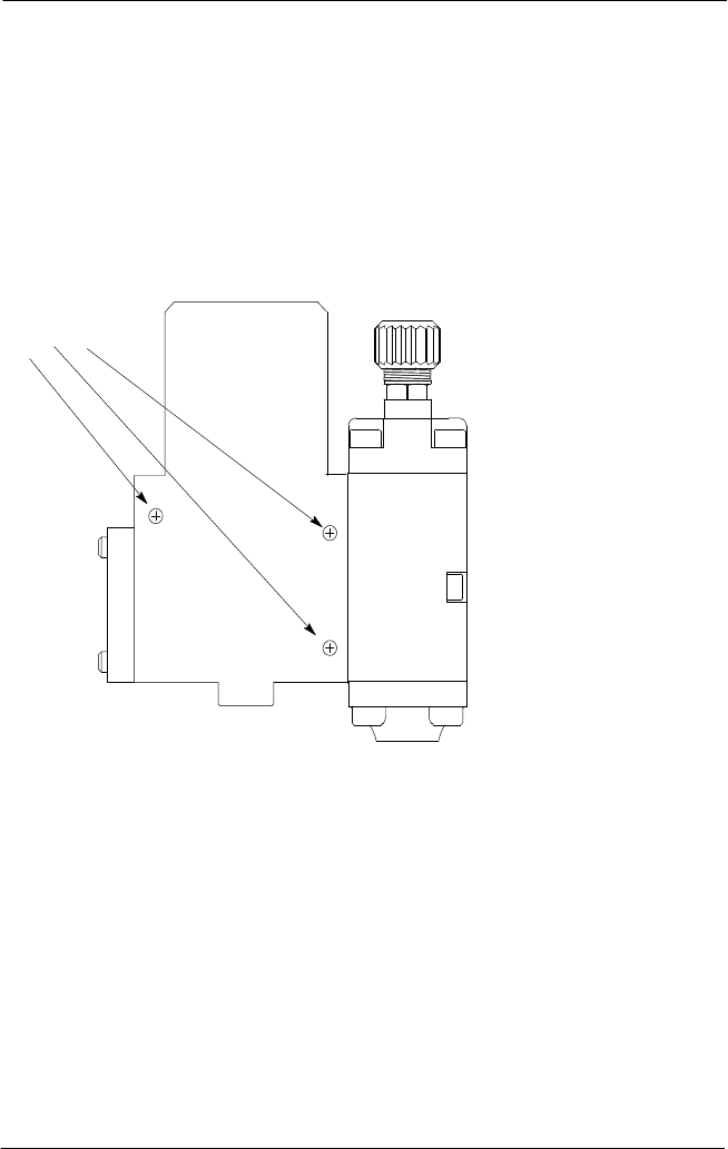
2. See Figure 27. Unplug the heater cordset from the hose or extension cable, remove the
three socket head screws, pull the applicator assembly away and separate the heater
assembly from the applicator.
M5 Screw
Figure 27: AG-900+/AG900+S Applicator
3. See Figure 28. Remove the two pan head screws (3) and the heated cover (2).
4. Remove the ground screw assembly (5).
NOTE: The heater cartridges are wired in parallel. Note their connections before
proceeding.
5. Remove the two porcelain wire connectors (4) that secure heater leads to the cordset
leads, separate the leads, and then pull the heater cartridges (1) from the heater body
(6).