SOM-1732-001.pdf - 第13页
[Disable] Button No alarm for component remainder is issued. Data Input Range 0 to 9999 Depending on the option selected in the "Alarm for Component Re- mainder" group box, each value represents number of compo…
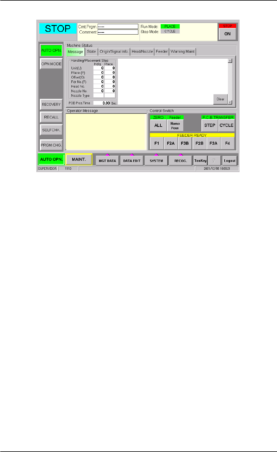
Fig. 4
*2 "Alarm for Component Remainder" Group Box
An alarm for component remainder can be issued according to the
component remainder data which is read for each feeder.
The alarm message "Alarm for Component Remainder" appears in
the "Operator Message" pane and the feeder No. related to the alarm
can be checked in the "ACV Check Status" tab sheet.
[Comp Remainder] Button
When the value under "Comp Rem" becomes smaller than the
specified one in the "ACV Check Status" tab sheet, an alarm for
component remainder is issued.
[P.C.B. Remainder] Button
When the value under "PCB Rem" (the estimated number of P.C.B.'s
which can be produced using the loaded components) becomes
smaller than the specified one in the "ACV Check Status" tab sheet,
an alarm for P.C.B. remainder is issued.
[Comp Feed Rem Tm] Button
When the value under "Feed Rem Tm" (the period of time during
which the loaded components can be supplied, that is, the time in
which the components are used up) becomes smaller than the speci-
fied one in the "ACV Check Status" tab sheet, an alarm for remain-
ing feed time is issued.
The time to be specified must be expressed in minutes.
As the time is calculated based on the time required to finish one
P.C.B., it may differ from the time in which all components are actu-
ally used up.
0310-001 11
AIP01EGP
8.1 "Opn. Mode" Tab Sheet
ACV Check Mode

[Disable] Button
No alarm for component remainder is issued.
Data Input Range
0 to 9999
Depending on the option selected in the "Alarm for Component Re-
mainder" group box, each value represents number of components,
number of P.C.B.'s, or time (minutes).
When "Enable" is set for the ACV function, the alarm func-
tion for the component remainder becomes available.
Note
0310-001 12 AIP01EGP
8.1 "Opn. Mode" Tab Sheet
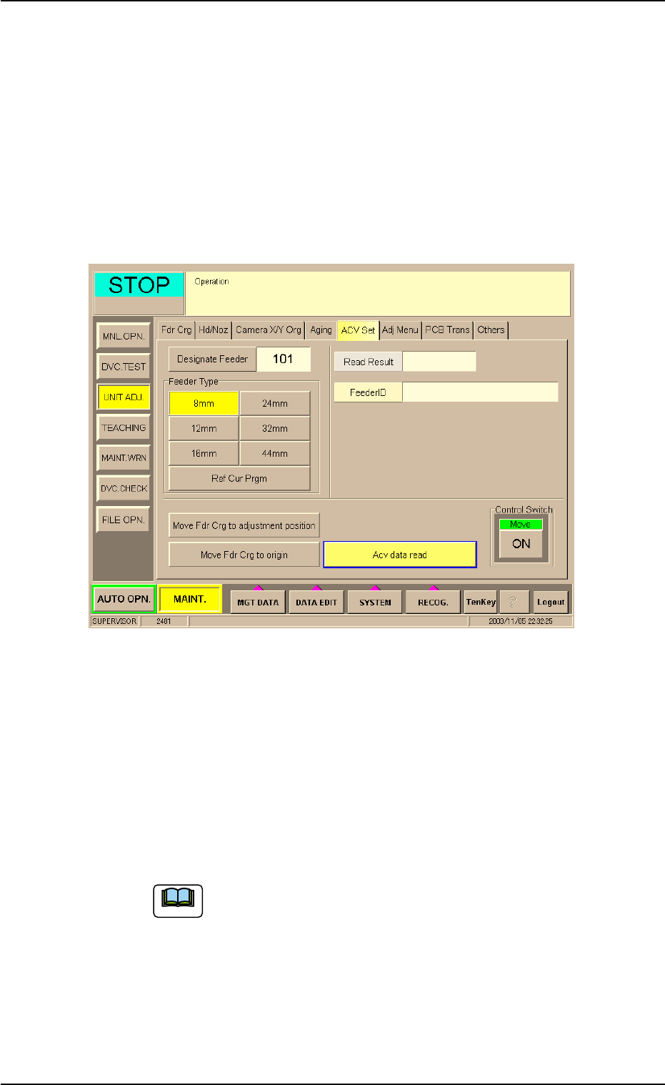
8.2 "ACV Set" Tab Sheet
This tab sheet enables the operator to adjust the ACV data reading sec-
tion (ACV antenna) and check the contents in the Tag memory.
Do not use this function in normal cases.
• Sheet Layout
When the "ACV Set" tab is pressed in the "UNIT ADJ." window
(submenu), the following tab sheet appears.
Fig. 5
Procedure for ACV Adjustment
(1) Set parameters in the "Designate Feeder" and "Feeder Type"
text boxes.
The feeder No. and type must be specified for data reading.
• [Designate Feeder] Button
The data input range is "101 to 179", "201 to 279", "301 to 379", or
"401 to 479".
The tab sheet looks different according to the selected
machine type.
8.2 "ACV Set" Tab Sheet
Note
0310-001 13 AIP01EGP