SOM-1732-001.pdf - 第15页
• Feeder T ype Select one of the following buttons to specify the feeder type. [8 mm] , [12 mm] , [16 mm] , [24 mm] , [32 mm] , [44 mm] , [Ref Cur Prgm] When the [Ref Cur Prgm] button is selected, the tape width of the s…
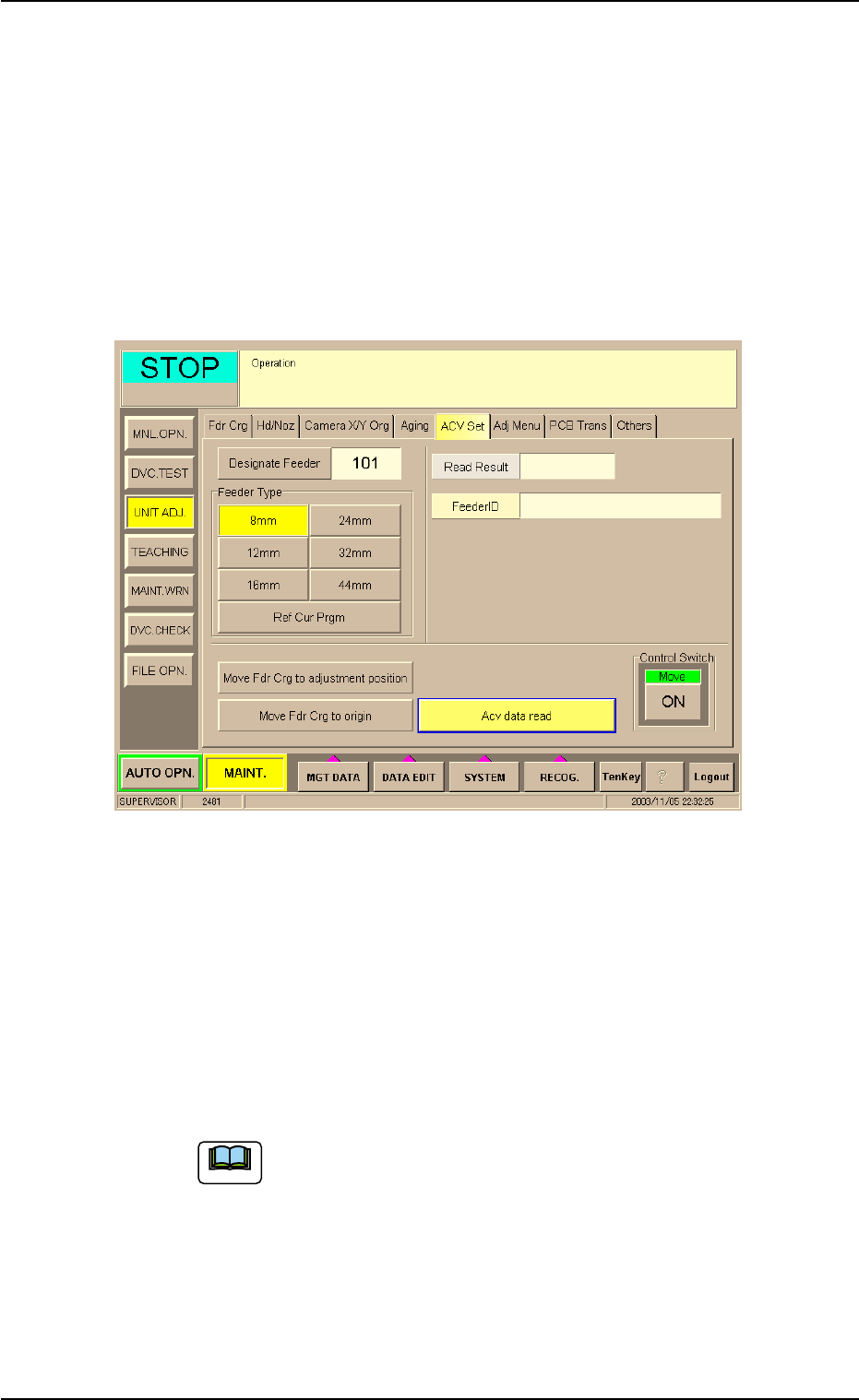
8.2 "ACV Set" Tab Sheet
This tab sheet enables the operator to adjust the ACV data reading sec-
tion (ACV antenna) and check the contents in the Tag memory.
Do not use this function in normal cases.
• Sheet Layout
When the "ACV Set" tab is pressed in the "UNIT ADJ." window
(submenu), the following tab sheet appears.
Fig. 5
Procedure for ACV Adjustment
(1) Set parameters in the "Designate Feeder" and "Feeder Type"
text boxes.
The feeder No. and type must be specified for data reading.
• [Designate Feeder] Button
The data input range is "101 to 179", "201 to 279", "301 to 379", or
"401 to 479".
The tab sheet looks different according to the selected
machine type.
8.2 "ACV Set" Tab Sheet
Note
0310-001 13 AIP01EGP

• Feeder Type
Select one of the following buttons to specify the feeder type.
[8 mm] , [12 mm] , [16 mm] , [24 mm] , [32 mm] , [44 mm] , [Ref
Cur Prgm]
When the [Ref Cur Prgm] button is selected, the tape
width of the specified feeder can automatically be re-
ferred to.
(2) Press the [ENABLE] button in 2 seconds after the [Move Fdr Crg to
adjustment position] button and the [ON] button (entitled "Move").
The specified feeder moves to the position where the data can be
read.
(3) Press the [ENABLE] button in 2 seconds after the [ACV data read]
button and the [ON] button (entitled "Move").
The ACV data is read and the result appears in the "Read Result"
text box (located at the upper right field of the tab sheet).
(4) Press the [ENABLE] button in 2 seconds after the [Move Fdr Crg to
origin] button and the [ON] button (entitled "Move"). The feeder car-
riage starts moving to its origin.
8.2 "ACV Set" Tab Sheet
Note
0310-001 14 AIP01EGP
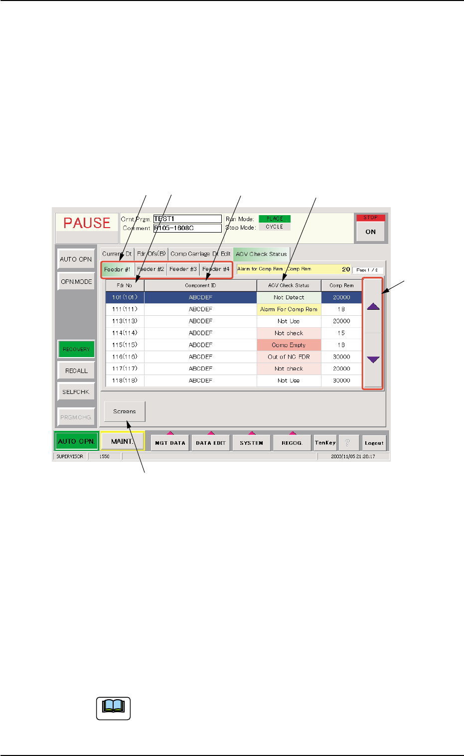
8.3 "ACV Check Status" Tab Sheet
This tab sheet is used to monitor the ACV check status and the read
data, and set the parameters for manual checking.
• Sheet Layout
When the "ACV Check Status" tab is pressed in the "RECOVERY"
window (submenu), the following tab sheet appears inside the win-
dow.
Fig. 6
*1 "Feeder #1", "Feeder #2", "Feeder #3", and "Feeder #4" Tabs
Each tab represents the corresponding feeder carriage.
*2 Fdr. No. (Actual Fdr No.)
Displayed are the feeder Nos. used for the current program and the
actual feeder Nos. in ( ).
*3 Component ID
Displayed are the component IDs of the placement feeder location
data related to the feeder No.
The displayed parameters are not those read from the Tag
memory.
8.3 "ACV Check Status" Tab Sheet
*1 *2 *3 *4
*5
*6
Note
0310-001 15 AIP01EGP