SOM-1732-001.pdf - 第18页
Fig. 7 *7 Comp Rem Displayed is the component remainder data that was read from the T ag memory . When the [Enable] button is selected in the "Record Component Remainder" group box, one piece of component is su…
*4 ACV Check Status
Displayed is the ACV check status.
Table 5
Items Status
Not check The ACV checking is not being made.
Finished Check The component ID identical to the information in the ACV line server
was detected during the ACV checking.
Comp Empty A component shortage error was detected during the ACV checking.
It is required to register the component.
Out of NC FDR The component ID nonidentical to the information in the ACV line server
was detected during the ACV checking.
Not Register A feeder provided with components not registered in the ACV line server
was detected.
Not Use Not used in the pattern program.
*5 [ ] and [ ] Buttons
The up or the down arrow can be pressed to scroll up or down the
tab sheet to expose hidden items.
*6 [Screens] Button
When this button is pressed, another tab sheet appears.
8.3 "ACV Check Status" Tab Sheet
0310-001 16 AIP01EGP
Note
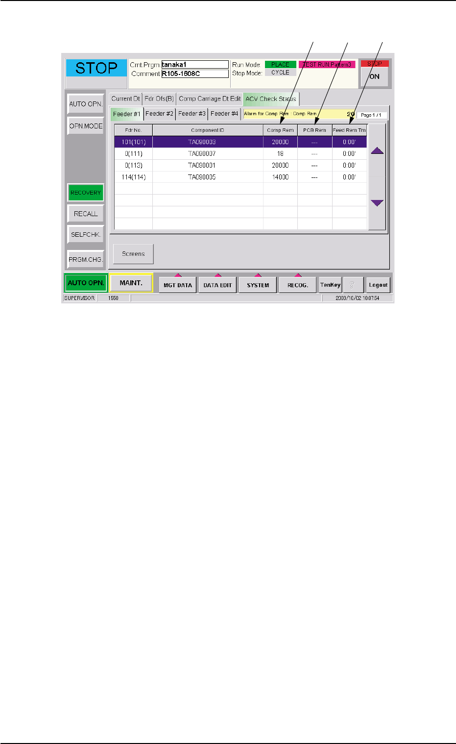
Fig. 7
*7 Comp Rem
Displayed is the component remainder data that was read from the
Tag memory.
When the [Enable] button is selected in the "Record Component
Remainder" group box, one piece of component is subtracted from
the remainder data every time a component is picked up during au-
tomatic operation.
When the [Comp Remainder] button is selected in the "Alarm for
Component Remainder" group box and the value under "Comp Rem"
is smaller than the specified one, the background color of the nu-
merical value turns yellow.
When the machine is powered or a program change operation is
performed, "---" appears.
8.3 "ACV Check Status" Tab Sheet
*7
*8
*9
0310-001 17 AIP01EGP

*8 PCB Rem
Displayed is the number of P.C.B.'s that can be produced when a
production is initiated according to the current pattern program and
using the components remaining in each feeder.
Since the number of remaining components is divided by the num-
ber of components to be used for one P.C.B., it is required to cor-
rectly set the number of remaining components.
This value decreases when the number of remaining components
is lessened during automatic operation.
When "Enable" is set for the ACV function, the [PCB Remainder]
button is selected in the "Opn. Mode" tab sheet, and the value for
"PCB Rem" is smaller than the specified one, the background color
of the numerical value turns yellow.
When the machine is powered or a program change operation is
performed, "---" appears.
PCB Rem (Estimated) =
Number of Remaining Components/
Number of Components Used for One P.C.B.
*9 Feed Rem Tm
Displayed is the period of time during which the components can be
fed when a production is initiated according to the current pattern
program and using the components remaining in each feeder. (Time:
Minutes)
Since the number of remaining components (estimated) is multi-
plied by the time required to finish one P.C.B., it is required to cor-
rectly set the number of remaining components.
This value decreases when the number of remaining components
is lessened during automatic operation.
When the [Enable] button is selected in the "ACV Mode" group box
and [Comp Feed Rem Tm] button in the "Alarm for Component Re-
mainder" group box of the "Opn Mode" tab sheet and the value un-
der "Feed Rem Tm" is smaller than the specified one, the back-
ground color of the numerical value turns yellow.
When the machine is powered or a program change operation is
performed, "---" appears.
Feed Remainder Time (Estimated) =
Number of Producible P.C.B.'s (Estimated)
××
××
×
Time Required to Finish One P.C.B.
8.3 "ACV Check Status" Tab Sheet
0310-001 18 AIP01EGP