Apollo1_Operators_Manuel.pdf - 第82页
82 cab - Produkttechnik GmbH / Tharo Systems, Inc. If you have switched the operating voltage of your rewinder you need to replace the fuses. For the standard setting of 230V , two fuses rated at 500mA T must be used. Fo…
81
cab - Produkttechnik GmbH / Tharo Systems, Inc.
Set the switch (5) to the required method of rewinding :
- Rewind with labels on the outer side of the silicon liner
- Rewind with labels on the inner side of the silicon liner
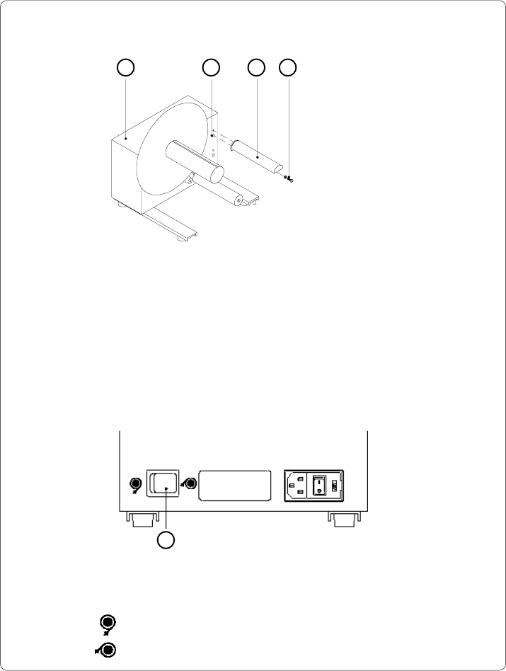
Mounting the Guide Bar
1 2 3 4
1 - Rewinder
2 - Upper threaded hole
3 - Guide bar
4 - Screw (incl. washer)
Fig. 13 c Mounting the guide bar
Using the hex screw (4) and washer provided, secure the guide bar (3) into the
upper one of the two threaded holes (2) located on the inside of the rewinder's side
cover. A hexagonal wrench is provided.
Selecting the Method of Rewinding
The external rewinder allows rewinding of labels in both ways, inside and
outside winding.
5
Fig. 13 d Selecting the method of rewinding
82 cab - Produkttechnik GmbH / Tharo Systems, Inc.
If you have switched the operating voltage of your rewinder you need to
replace the fuses. For the standard setting of 230V, two fuses rated at
500mAT must be used. For operation at 115V, two fuses rated at 1AT must
be used. (Both types of fuses are shipped with the rewinder, one of
which is installed depending on the voltage setting.)
To alter the voltage, open the cover (3) and remove the voltage selector.
Replace the fuses as explained above. Slide the voltage selector back into the
power supply module so that the correct voltage is visible in the lid window.
Connect the rewinder to a grounded outlet using the power cable supplied in the
accessories package.
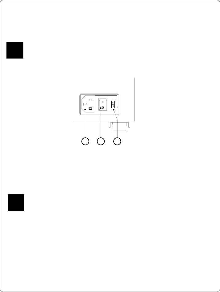
Connecting the Rewinder to the Power Supply
The rewinder operates with a supply voltage of 230V/ 50Hz or 115V/ 60Hz.
Before connecting the rewinder to the power supply, make sure that the
voltage selected on the power supply module is the same as your main
power supply !
Fig. 13 e Power supply module of the external rewinder
1 - Power supply
connector
2 - Power switch
3 - Voltage selector cover
The current voltage setting of the power module is visible in the lid window (3).
F
1 2 3
F
83
cab - Produkttechnik GmbH / Tharo Systems, Inc.
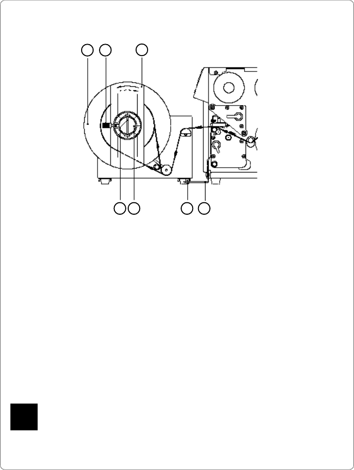
Rewinding Directly onto the Rewind Axle
Fig. 13 f Rewinding directly onto the rewind axle
1. Attach the rewinder to the Apollo by positioning the metal posts on the
bottom of the rewinder (5) into the holes of the adapter plate (4).
2. Feed the label strip over the guide bar and under the roller onto the
rewinder axle (6) as shown in Figure 13 f.
3. Considering the required method of rewinding, secure the label strip appro-
priately to the rewinder axle (6) by sliding the clamp (7) over the label strip
with the clamp set in the groove. (the broken line shows the path of inside
rolled labels)
Ensure that the label strip is even with the disc (1).
4. Slide the clamp (7) as far as possible towards the disc (1).
5. Slide the flange (3) onto the rewind axle (6) so that it slightly touches the
label strip. The label strip must be able to move slightly between the disc
and the flange.
6. Tighten knurled screw (2) in the flange (3).
7. Switch the rewinder ON.
Caution !
When switched ON, the rewinder immediately starts rotating !
21
3
457 6
F