00191270-03.pdf - 第17页
Retrofit Instructions Starting (Incrush ) current limiter SIPLACE S-20, F4, F 5 10/2005 Edition 17 2.5 Circuit diagrams / Power supply 2 Circuit diagram
Retrofit Instructions Starting (Incrush) current limiter SIPLACE S-20, F4, F5
10/2005 Edition
16
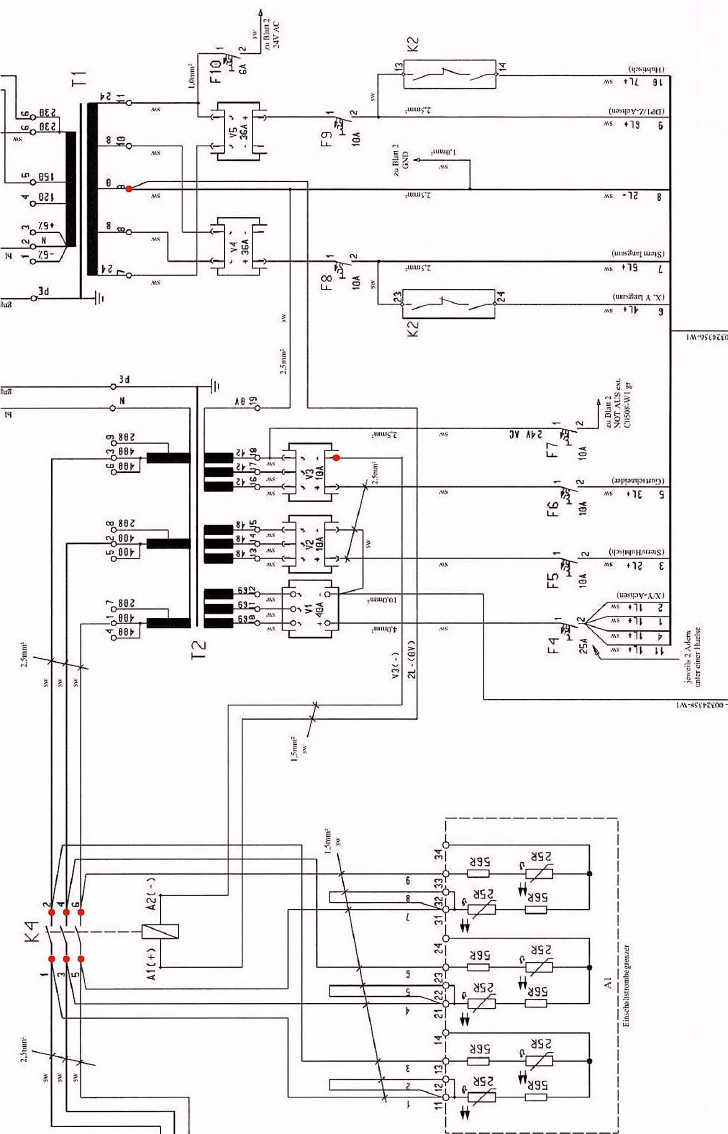
: Connect the previously marked wires 1, 3, 5 (Input) and 2, 4, 6 (Output) to contactor K4 1, 3,
5 (Input) and 2, 4, 6 (Output). (see circuit diagram).
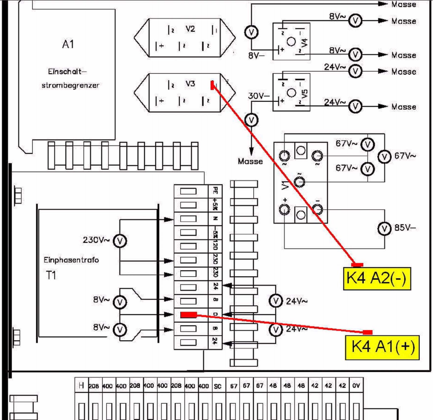
: Disconnect the wire at 0V-terminal (terminal No. 9) of single-phase transformer T1 and
squeeze it together with the connection from contactor K4 / A1 (+) under one wire-end sleeve
(doubled).
: Connect both wires with terminal No. 9 again. (see circuit diagram).
: Remove the empty plug at the output “-“ of the rectifier V3 and plug it into the connection from
contactor K4 / A2 (-). (see circuit diagram).
: Fix the wires to the single-phase transformer and to the rectifier with the cable fasteners.
: Slide the power supply unit back into the placement machine, mount the security screw and
the cover and reconnect the power supply.
: Switch on the placement machine at the main switch.
2
2
Retrofit Instructions Starting (Incrush) current limiter SIPLACE S-20, F4, F5
10/2005 Edition
17
2.5 Circuit diagrams / Power supply
2
Circuit diagram
Retrofit Instructions Starting (Incrush) current limiter SIPLACE S-20, F4, F5
10/2005 Edition
18
2
2
2
2
2
2
2
2
2
2
Connection of contactor K4