00195044-14_UM_VisionTeachStation_DE EN.pdf - 第125页
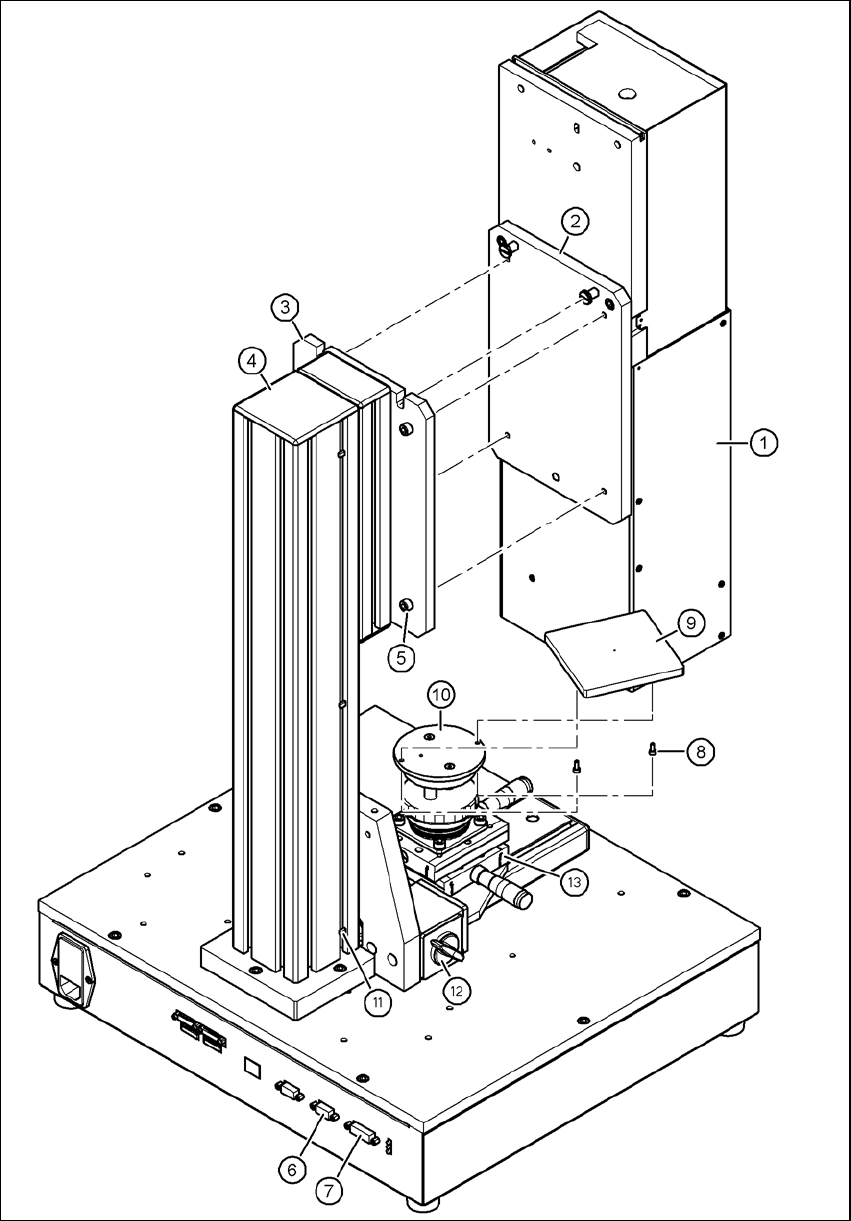
Vision Teach Station User Manual 5 Installing the cameras 05/2015 Edition 5.1 Installing stationary cameras, type 25, 33 and 36 125 5 Fig. 5.1 - 7 Fixing camera type 33 to the pillar
5 Installing the cameras Vision Teach Station User Manual
5.1 Installing stationary cameras, type 25, 33 and 36 05/2015 Edition
124
5.1.2.3 Fixing camera types 33, 36 and 25 to the pillar
Use the two special screws to fix the camera (item 1 in Fig. 5.1 - 7, page 125) in the cut-outs
in the mounting plate (item 3 in Fig. 5.1 - 7, page 125).
Fix the mount (item 2 in Fig. 5.1 - 7, page 125) to the mounting plate (item 3 in Fig. 5.1 - 7,
page 125) using the 4 hexagon socket head screws M6 x 20 (item 5 in Fig. 5.1 - 7, page 125).
WARNING 5
Make sure that the camera is attached firmly to the mounting plate (item 3 in Fig. 5.1 - 7, page
125). For safety reasons, it must be screwed to the mounting plate with the 4 hexagon socket
head screws M6 x 20.
Release the lock on the positioning unit (item 13 in Fig. 5.1 - 7, page 125 by turning the knob
(item 12 in Fig. 5.1 - 7, page 125) on the magnetic switch towards the pillar.
Push the positioning unit (item 13 in Fig. 5.1 - 7, page 125) out of the camera range.
Fix the component support (item 9 in Fig. 5.1 - 7, page 125) using the two hexagon socket head
screws M3 x 8 (item 8 in Fig. 5.1 - 7, page 125) to the holder (item 10 in Fig. 5.1 - 7, page 125).
After fitting the component support, lock the positioning unit once more.
Vision Teach Station User Manual 5 Installing the cameras
05/2015 Edition 5.1 Installing stationary cameras, type 25, 33 and 36
125
5
Fig. 5.1 - 7 Fixing camera type 33 to the pillar
5 Installing the cameras Vision Teach Station User Manual
5.1 Installing stationary cameras, type 25, 33 and 36 05/2015 Edition
126
Key to figure 5.1 - 7, page 125
(1) Camera, type 33, 36 or 25
(2) Mount, type 33/36 or 25
(3) Mounting plate
(4) Pillar
(5) Hexagon socket head screw M6 x 20, 4x
(6) X2: CAN bus connection for stationary camera
(7) X1: Power supply connection for stationary camera
(8) Hexagon socket head screw M3 x 8, 2x
(9) Component support, camera type 25/33/36, complete
(10) Holder for component support
(11) Cable ties, 3x
(12) Magnetic switch
(13) Positioning unit
5
5.1.3 Connecting camera type 33, 36 or 25
CAUTION 5
Make sure that the base module and PC are switched off before connecting any cables.
Connect connector X2 on cable 03040355-W2 to socket X2 (item 6 in Fig. 5.1 - 7, page 125)
on the base module.
Connect connector X1 on cable 03040355-W1 to socket X1 (item 7 in Fig. 5.1 - 7, page 125)
on the base module.
Plug the camera bus cable 03040359-xx into the RJ45 socket on the camera (item 2 in Fig. 5.1
- 2, page 120).
Connect the other end of the camera bus cable to the camera bus interface on the PC (item 1
in Fig. 4.3 - 2, page 117).
Fix the cables 03040355, W1 + W2 and 03040359-xx to the pillar using 3 cable ties
(item 11 and item 4 in Fig. 5.1 - 7, page 125).
Make sure that the bending radii of the cables are large enough and that there is little tension
so that the cables are not damaged.