ENG_SS_108-90801_E.pdf - 第4页
Product specification ‘ Multisprin g standard power ’ 108 - 90801 ..........................................................................................................................................................…
Product specification ‘Multispring standard power’ 108-90801
................................................................................................................................................................................................................................................…………………..
Rev. E Page 3 of 7
R1-1 (Rev. 02-00)
1.42
1.57
min 110
max 300
Product specification ‘Multispring standard power’ 108-90801
................................................................................................................................................................................................................................................…………………..
Rev. E Page 4 of 7
R1-1 (Rev. 02-00)
4. INFORMATION ON THE APPLICATION.
The Multispring as described can be used as a
Individual press-in termination.
Straight or right angle termination.
Rear plug up.
Wrapped connection.
Connector or module with pre-assembled press-in terminations.
5. INSTRUCTION AND TOOLS FOR THE PRESS-IN OPERATION.
Depending on plating combination minimum 1 replacement is guaranteed with a new press-in
termination.
More repairs have to be tested on request.
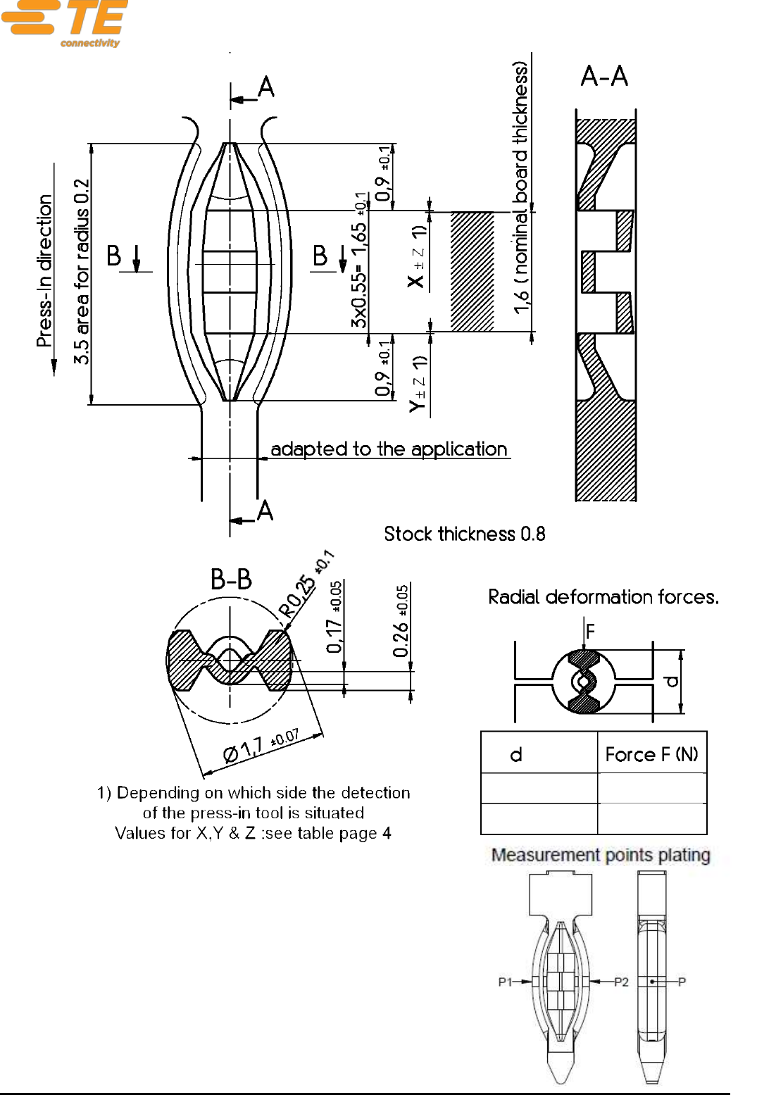
Press-in depth :
As on the dimensional drawing on page 3 for the minimum thickness printed board.
For thinner printed boards the position of the printed board should be situated in the middle of the
press-in zone. Notice that some press-fit parameters can be affected and have a lower performance
(e.g. Retention force) see also paragraph 2: ‘PCB definition’. In case of PCB’s with a smaller
thickness of 1.6mm nominal, a project specific test is recommended.
For thicker printed boards the position of the press-in zone should be preferably
in the middle or in the upper half of the printed board thickness. See the application drawing and
table.
For complex geometry with a high number of pins, the dimension of X±0.2mm can be interpreted of
the mean of all press-in depths. The maximum single press-in depth should however been within
Y±0.3mm.
PCB Thickness
Nominal Press-in
dimension X
Nominal Press-in
dimension Y
Tolerance Press-in
dimension Z
> 1.6 mm
0
0.2 (0.3 *)
1.6 mm
0
0
1.2…1.6 mm
0.1 - k
0.1 – k
With k = (1.6 – PCB Thickness) / 2
*) For complex applications with a high number of pins, the tolerance Z of ±0.2 mm can be extended
towards ±0.3 mm. The mean of all press-in dimensions of the application should however still lay
within the ±0.2 tolerance range.
For standalone pins as Single Pin Insertion, the depth tolerance of
+0.2 mm to -0.2 mm is mandatory.
The use of the middle of the Multispring as reference for press-in depth will be less accurate and is
not recommended. One should choose between dimension X or Y to define the right press-in depth
dimension. This choice of reference is determined by the application (housing, module, stand-alone
pin…) and the used press-in tooling (detection, reference side of the PCB,…). In that way the usual
big tolerances of the PCB thickness can be avoided to optimize the press-in process and the
tolerance calculation chain.
Product specification ‘Multispring standard power’ 108-90801
................................................................................................................................................................................................................................................…………………..
Rev. E Page 5 of 7
R1-1 (Rev. 02-00)
The use of a lubricant, anti-tarnish or other post treatments on the Multispring zone can influence the
performance negatively and should therefore be avoided.
Press in force / distance should be controlled.
Press-in speed:
Recommended maximum 5 mm/s for header applications. For stitched pins speeds up to 600 mm/s
are in use. As extreme high speeds can influence the press-in behaviour, an application specific
check is recommended. Higher speeds are likely possible but needs to be tested.
Tool information :
The press-in tool has to be adapted to the actual application. To ensure an optimal quality of the
applied TE connectivity products, we recommend the utilization of application equipment from TE
connectivity.
The latest news and detailed information on application tooling can be found on
https://www.te.com/global-en/products/application-tooling.html
Contact person: siegfried.beck@te.com or TAC-EMEA@te.com
6. PRESS-IN CHARACTERISTICS.
6.1 Mechanical
Maximum press-in forces (performed on single multispring termination):
Plating multispring
Max. press-in forces
Typical
a)
Min. press-in forces
SnPb
160N a)
120-130N
40N
Sn
185N a)b)
125-150N
40N
In
200N a)b)
110-140N
40N
Ag
tbd
tbd
tbd
Au
tbd
tbd
tbd
a) in PCB with Chemical Sn
b) in PCB with Cu+OSP
Minimum push-out force per termination: 40 N (typical values 70-80N)
Values in other printed boards: have to be tested on request.
6.2 Electrical
Contact resistance < 0.5 m (measured values acc IEC 60352-5 in tin plated printed boards)
Derating (measured values acc IEC512-3 in 1.6 tin plated printed boards)