M1_ServiceManual_e.pdf - 第19页
2 Periodical Checks 2-1 2 Periodical Checks
1 Installation
1-11
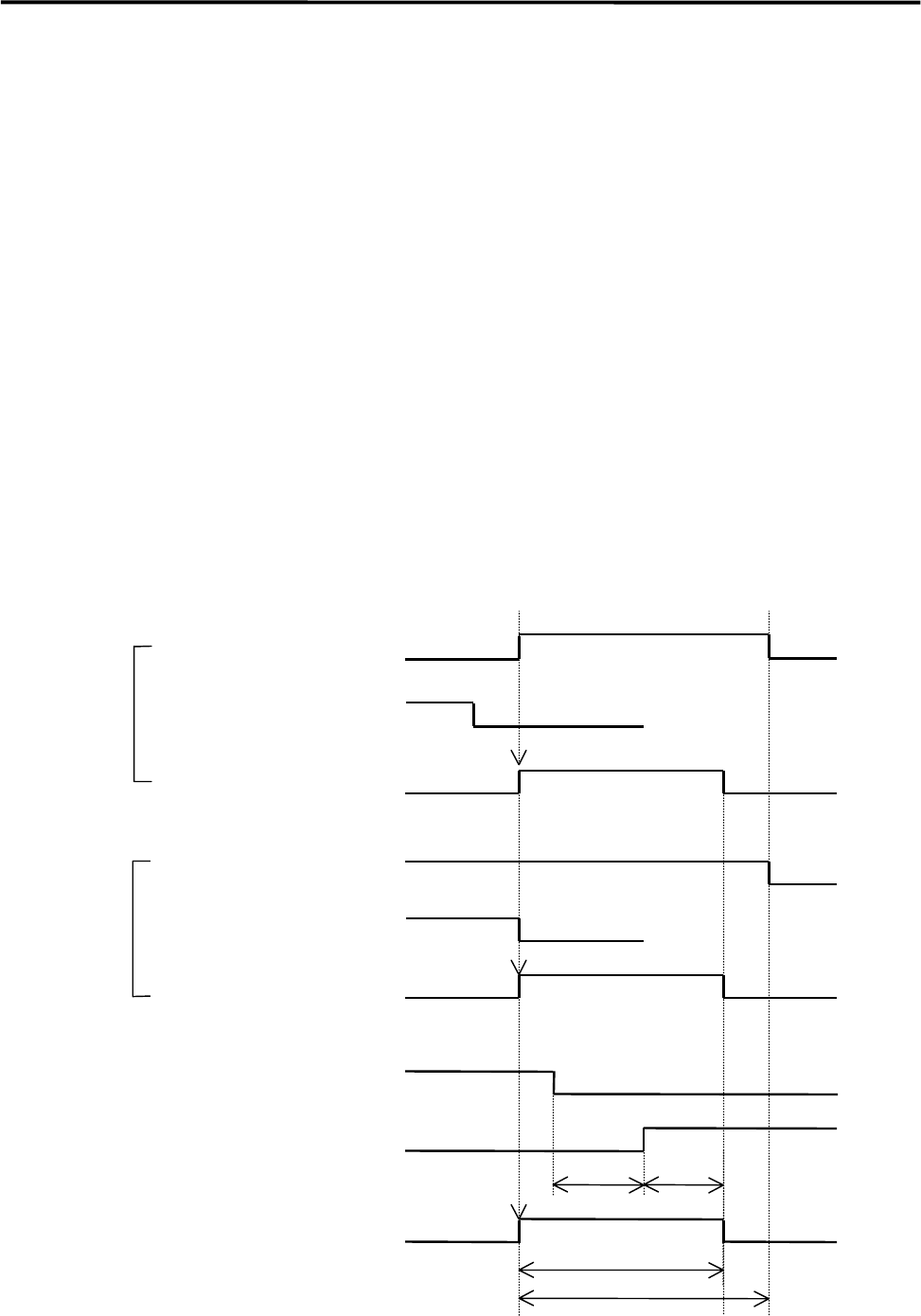
Sequence of Sending PC board (SMEMA Interface spec.)
① When component placements have been finished, the mounter becomes ready to send out the PC
board.
② The mounter starts to send out signals through BOARD AVAILABLE line to the post-process and the
conveyor is activated when the mounter receives signals through MACHINE NOT READY line from
the post-process under the condition described in 1.
③ The board stopper will be activated after the arrival sensor has been deactivated and the time set at
WAIT-1 has passed.
④ The mounter stops to send out signals through BOARD AVAILABLE line and the conveyor is
deactivated after the board stopper was activated and a certain time (preset in TIMER) has passed.
⑤ If the conveyor will not be deactivated within 10 seconds after it was activated, an error
[CONVEYOR TROUBLE] will result.
⑥ If the mounter continues to receive signals through MACHINE NOT READY line after the conveyor
was activated and the time set at WAIT-16 has passed, an error [I/F TROUBLE (POST-PROCESS)]
will result
⑦ Pressing START button restarts the operation paused by the error.
MACHINE NOT READY
BOARD AVAILABLE
MACHINE NOT READY
CONVEYOR
ARRIVAL SENSOR
BOARD STOPPER
PLACEMENT
⑥
⑤
ON
TIMERWAIT-1
END
RUN
ENDRUN
OR
PLACEMENT
BOARD AVAILABLE

2 Periodical Checks
2-1
2
Periodical Checks

2 Periodical Checks
2-2
Daily Checks
Visual Check
Check the followings before turning on the main switch and power switch of the mounter.
NOTE: Power source and air supply must be in the ON state.
ITEM DESCRIPTION
Temperature and Humidity
Make sure temperature is in the range of 15 to 35 deg. and humidity 45 to 60%
(non-condensing).
Room Environment
If air is dusty, check air filters.
If mounter surface rusts as a result of corrosive gas, check vents, reflow ovens,
and board cleaners.
Air Supply
Make sure air pressure of regulator is 0.49 MPa (5kg/cm
2
).
If drain cock contains water, drain it. (Adjusting temperature of dry air may be
required.)
If drain contains oil, investigate the cause.
Reject Tray (Front & Rear)
Make sure of the setting direction of the reject tray.
Make sure that the ends of the reject tray and the tape guide (on which station No.
sticker is placed) meet.
Make sure that the reject tray sits properly and is not lifted by electronic
components.
Conveyor
Make sure conveyor width of all the peripherals are the same.
Make sure no obstacles are on conveyor.
Head Moving Range
Make sure no obstacles are in head moving range, e.g. on the adjust plate.
Scan Camera
Check mirror for dirt and flaw. Clean if dirty.
Note: If dust settles or condensation occurs on the mirror, the reflectance drops,
causing illumination to need to be brighter. This may lead to a drop of recognition
rate. To avoid this, always keep the mirror clean.
)
”Camera” in 3 Mechanical Section.
Fixed Camera
Make sure no obstacles are on fixed camera.
ANC
Make sure no obstacles are around ANC tower.
Nozzle
Clean nozzles if dirty. Replace if deformed.
Feeder Bank
Clean front and rear feeder banks.
Make sure tape feeders are set on bank securely. If not, it may cause head
collision.