00195044-11_UM_VisionTeachStation_DE EN.pdf - 第114页
3 Ordering information and package supplied Vision Teach Station User Manual 3.2 Cameras and assembly kits 11/2013 Edition 114 NOTE 3 Figure 3.2 - 8 , page 1 13 , shows the position at which the component camera (item 1)…
Vision Teach Station User Manual 3 Ordering information and package supplied
11/2013 Edition 3.2 Cameras and assembly kits
113
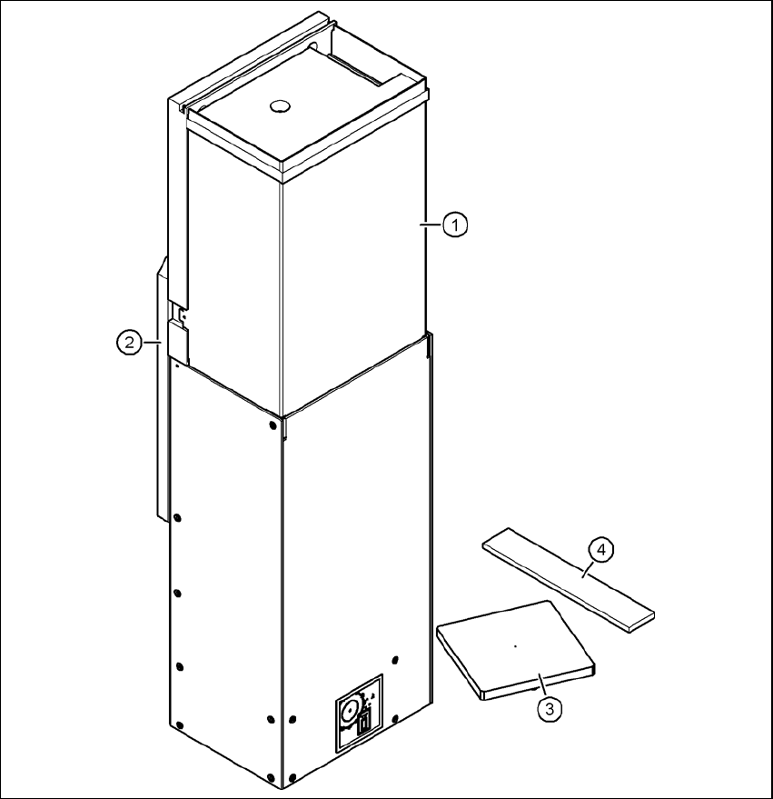
3.2.6 Camera, type 36 with assembly kit - item no. 03054654-xx (option)
3
3
Fig. 3.2 - 8 Camera type 36 - parts
3
(1) Component camera, stationary, P&P, type 36, 32 x 32, digital, item no. 03042491-xx
(2) Mount for camera, type 33/36, item no. 03039467-xx
(3) Component support, camera type 25/33/36, complete, item no. 03039504-xx
(4) Focus point adjustment guide, camera type 33/36, item no. 03046391-xx
Cable set for vision teach station, stationary, item no. 03040355-xx

3 Ordering information and package supplied Vision Teach Station User Manual
3.2 Cameras and assembly kits 11/2013 Edition
114
NOTE 3
Figure 3.2 - 8, page 113, shows the position at which the component camera (item 1) is mounted
on the vision teach station. The camera is turned 180° about the horizontal on the placement
machine. Only components that are no larger than the field of vision of the component camera
(single measurement) can be taught at the vision teach station. Multiple measurements must be
taken on the machine. Detection of the orientation of asymmetrical package forms is not suppor-
ted on the vision teach station.

Vision Teach Station User Manual 4 Setting up the vision teach station
11/2013 Edition 4.1 Requirements for the installation site
115
4 Setting up the vision teach station
4.1 Requirements for the installation site
4.1.1 Ambient conditions
The vision teach station is approved for use in production and in the office. The area around it must
be clean and free from dust.
4.1.2 Electrical connection
4
Tab. 4.1 - 1 Electrical ratings
4
4.1.3 Set-up location for the base module
CAUTION 4
The base module weighs around 30 kg.
You should therefore place the base module on a stable surface that is clean and level.
Two people will be needed to move the base module because of the weight.
Component Supply voltage
Base module 100 VAC to 240 VAC, 50/60 Hz
PC with wide-range power supply
PC with 115 VAC/230 VAC changeover switch
100 VAC to 240 VAC, 50/60 Hz
100 VAC to 127 VAC, 200 VAC to 240 VAC
TFT monitor with wide-range power supply 100 VAC to 240 VAC, 50/60 Hz