00195044-11_UM_VisionTeachStation_DE EN.pdf - 第174页
10 Exchange of data between the vision teach station and the production line Vision Teach Station User Manual 10.2 Measurement contexts 11/2013 Edition 174 With the "Automatically update measurement contexts of the …
Vision Teach Station User Manual 10 Exchange of data between the vision teach station and the production line
11/2013 Edition 10.2 Measurement contexts
173
10.2.5.1 Local storage of the station measurement contexts
All station measurement contexts are stored in a structured root folder. C:\SIPLACE Vision is pre-
installed. The root folder is configurable. 10
Folders are added for each SIPLACE Pro server in the root folder. Under each SIPLACE Pro
server, folders are added for each station of the SIPLACE Pro server. 10
The station measurement contexts are stored in the station folders.
The information of the folders is loaded when the SIPLACE Vision Teach Station is started. The
station measurement contexts can be displayed in the SIPLACE Vision Teach Station although
the SIPLACE Pro server is offline.
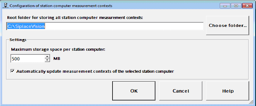
The following dialog to configure the local storage of the station measurement contexts can be
started in the "Configuration -> Station computer measurement contexts..." menu.
Fig. 10.2 - 2 Configuring the local storage of station measurement contexts
If another root folder is selected, all information and folders of the SIPLACE Pro server and the
station computers will be copied to the new folder.
After query, existing measurement contexts will be copied, as well.
Under "Maximum storage space per station computer", the space size for storing the local
measurement contexts of each station may be specified.
Minimum storage space = 100 MB, default value = 500 MB.
The storage space is checked whenever new measurement contexts are copied from the station
computer. If the maximum storage space has been exceeded, a dialog is displayed in which the
user can decide to delete the oldest measurement contexts automatically. In this case, the respec-
tively oldest measurement context will be deleted until the occupied storage space lies within the
allowed range.
10 Exchange of data between the vision teach station and the production line Vision Teach Station User Manual
10.2 Measurement contexts 11/2013 Edition
174
With the "Automatically update measurement contexts of the selected station computer" setting a
check for new available measurement context files on the station computer will always be per-
formed for a selected station in the "Measurement contexts" view. New available measurement
context files will be automatically copied.
This setting should be disabled if it is undesirable that the SIPLACE Vision Teach Station connects
to the station computer to check the measurement contexts each time a station is new selected
in the "Measurement contexts" view.

Vision Teach Station User Manual 11 Measuring components
11/2013 Edition 11.1 Preparing components for the measurement
175
11 Measuring components
11.1 Preparing components for the measurement
11.1.1 Placing the component on the component support
Release the lock on the positioning unit (item 2 in Fig. 11.1 - 1, page 177) using the magnetic
switch (item 2 in Fig. 11.1 - 1, page 177).
Push the positioning unit (item 2 in Fig. 11.1 - 1, page 177) outwards out of the range of the
component camera (item 7 in Fig. 11.1 - 1, page 177).
On the component support (item 5 in Fig. 11.1 - 1, page 177), the center point is identified by
a mark (item 6 in Fig. 11.1 - 1, page 177).
Place the component on the component support so that the middle of the component tallies
with the center point of the component support (item 6 11.1 - 1, page 177).
Place components with leads or balls on their backs. The leads or balls should point up to the
camera.
Only use double-sided adhesive tape between the support and component to secure the com-
ponent and prevent it slipping if absolutely essential.
Make sure that the white adhesive tape does not project over the body of the component. This
could corrupt the measurement.
Turn the component support so that the edges of the component are parallel to the camera
edges.
Make sure that the coordinate systems are aligned correctly (see chapter 12, page 182).
Push the positioning unit until the middle of the component is roughly under the camera.
Hold the focus point adjusting guide against the bottom edge of the camera.
Turn the adjusting ring (item 4 in Fig. 11.1 - 1, page 177) up until the component just stops
touching the adjusting guide.
Carefully pull the positioning unit back and remove the adjusting guide (see Fig. 11.1 - 2, page
178).
Be careful not to damage the component.
PLEASE NOTE: 11
The focus point must be set with an accuracy < ± 0.4 mm, otherwise the component will be
mapped too large or too small.
Each camera has its own adjustment guide for the focus point (see section 3.2, from page
106). The focus distances are listed in section 13, page 184. 11