00195044-11_UM_VisionTeachStation_DE EN.pdf - 第123页
Vision Teach Station User Manual 5 Installing the cameras 11/2013 Edition 5.1 Installing stationary cameras, type 25, 33 and 36 123 5.1.2 Installing the camera on the base module 5.1.2.1 T ools required Allen key , set 5…
5 Installing the cameras Vision Teach Station User Manual
5.1 Installing stationary cameras, type 25, 33 and 36 11/2013 Edition
122
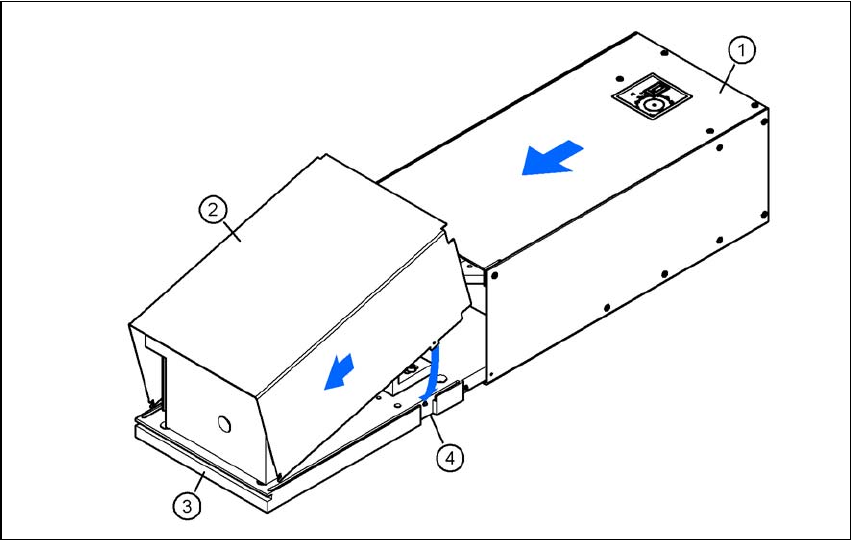
5.1.1.3 Assembling the camera
Slide the cover (item 2) nose-first into the base plate (item 3).
Swivel the cover down until it engages on the ball catch (item 4) in the base plate (item 3).
Slide the illumination head (item 1) back until it engages.
5
Fig. 5.1 - 5 Assembling the camera
Vision Teach Station User Manual 5 Installing the cameras
11/2013 Edition 5.1 Installing stationary cameras, type 25, 33 and 36
123
5.1.2 Installing the camera on the base module
5.1.2.1 Tools required
Allen key, set
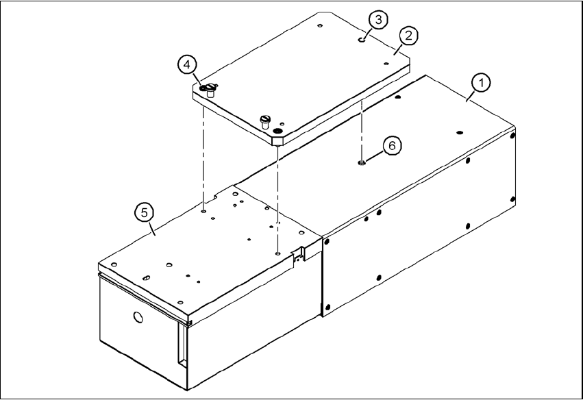
5.1.2.2 Fitting the mount for camera types 33, 36 and 25
Turn the camera 180° about its long axis so that the base plate (item 5) is pointing up.
Place the mount (item 2) on the camera so that the parallel pin (item 3) slides into the hole (item
6) in the illumination head (item 1).
Fix the mount (item 2) to the base plate (item 5) using the two hexagon socket head screws
M6 x 16 (item 4).
The illumination head can no longer become detached from the base module.
5
Fig. 5.1 - 6 Fitting the mount for camera type 33
(1) Illumination head
(2) Mount for type 33/36, item no. 03039467-xx; mount for type 25, item no. 03039471-xx
(3) Parallel pin
(4) Hexagon socket head screw M6 x 12, 2x
(5) Base plate
(6) Hole for parallel pin

5 Installing the cameras Vision Teach Station User Manual
5.1 Installing stationary cameras, type 25, 33 and 36 11/2013 Edition
124
5.1.2.3 Fixing camera types 33, 36 and 25 to the pillar
Use the two special screws to fix the camera (item 1 in Fig. 5.1 - 7, page 125) in the cut-outs
in the mounting plate (item 3 in Fig. 5.1 - 7, page 125).
Fix the mount (item 2 in Fig. 5.1 - 7, page 125) to the mounting plate (item 3 in Fig. 5.1 - 7,
page 125) using the 4 hexagon socket head screws M6 x 20 (item 5 in Fig. 5.1 - 7, page 125).
WARNING 5
Make sure that the camera is attached firmly to the mounting plate (item 3 in Fig. 5.1 - 7, page
125). For safety reasons, it must be screwed to the mounting plate with the 4 hexagon socket
head screws M6 x 20.
Release the lock on the positioning unit (item 13 in Fig. 5.1 - 7, page 125 by turning the knob
(item 12 in Fig. 5.1 - 7, page 125) on the magnetic switch towards the pillar.
Push the positioning unit (item 13 in Fig. 5.1 - 7, page 125) out of the camera range.
Fix the component support (item 9 in Fig. 5.1 - 7, page 125) using the two hexagon socket head
screws M3 x 8 (item 8 in Fig. 5.1 - 7, page 125) to the holder (item 10 in Fig. 5.1 - 7, page 125).
After fitting the component support, lock the positioning unit once more.