00192790-01.pdf - 第41页
User Manual SIPLAC E S-25 HM / HS-50 2 PCB Camera Mu lticolor (Option) Software Version S C.502.xx 11/00 Issue 2.3 Focus Heigth: Install/Remove the Distance Plate 41 .H\ 1. PCB ca mera Mul ticol or 2. Fas teners: 3 h…
2 PCB Camera Multicolor (Option) User Manual SIPLACE S-25 HM / HS-50
2.3 Focus Heigth: Install/Remove the Distance Plate Software Version SC.502.xx 11/00 Issue
40
.H\
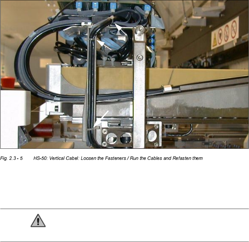
1. 3 Cable ties
CAUTION
Make certain that no screws, bolts, etc., fall into the machine.
Å CAREFULLY undo the cable ties on S-50 and S-25 HM as shown above.
Å In addition, remove the cable clamps (Allen wrench size 2.5 and 3) on the S-25 HM.
User Manual SIPLACE S-25 HM / HS-50 2 PCB Camera Multicolor (Option)
Software Version SC.502.xx 11/00 Issue 2.3 Focus Heigth: Install/Remove the Distance Plate
41
.H\
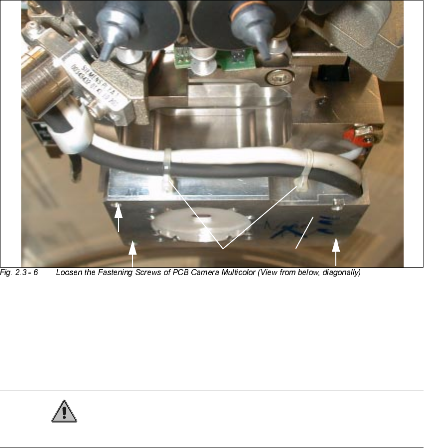
1. PCB camera Multicolor
2. Fasteners: 3 hex head cap screws M3 x 14 (captive)
3. 2 Cable ties (do not remove !)
CAUTION
Do not pull on the cables while work is in process.
Å Touch the PCB camera Multicolor only on its circumference and hold the camera tight AT ALL
TIMES.
Å Working from the bottom, use a screwdriver for hex head cap screws to undo the 3 fastening
screws M3 x 14 (captive) on the PCB camera Multicolor.
Å To prevent damage to the cables or the camera, continue to hold the camera and just move it
far enough down as absolutely imperative to insert/remove the distance plate.
2
2
21
3
2 PCB Camera Multicolor (Option) User Manual SIPLACE S-25 HM / HS-50
2.3 Focus Heigth: Install/Remove the Distance Plate Software Version SC.502.xx 11/00 Issue
42
.H\
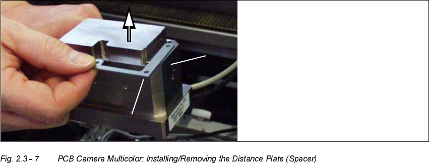
1. PCB camera Multicolor (dismantled)
2. Distance plate (supplied with product or installed while the option is being retrofitted)
Å Remove the distance plate or place it on the camera assembly surface in the correct rotational
position (depends on the holes and the outside contour).
Å Working from below, place the PCB camera Multicolor with or without distance plate, as re-
quired, in the correct position
- on the assembly surface of the camera holder (S-25 HM) or
- on the 3 spacer pieces in the camera holder (HS-50)
Å Screw the camera tight with the 3 captive hex head cap screws M 3 x 14.
Å Fasten the cables leading upward such that the
ORDG
on the plug-type sockets
LVUHOLHYHG
– as shown for HS-50 in Fig. 2.3 - 5.
You will need cable ties or this purpose.
– as show for S-25 HM in Fig. 2.3 - 4.
For this you will require size 6 cable clamps and the M3 and M4 screws removed earlier.
Å Remove all of the tools, etc., from the machine’s working area.