00192790-01.pdf - 第44页
2 PCB Camera Multicolor (Option) User Manual SIPLACE S-25 HM / HS-50 2.4 LCU: Configuration PCB Camera Multicolor Software Version SC.502.xx 11/00 Issue 44 / &8&RQILJXUDWLRQ3&%&DPHUD0XOWL FRORU T…

User Manual SIPLACE S-25 HM / HS-50 2 PCB Camera Multicolor (Option)
Software Version SC.502.xx 11/00 Issue 2.3 Focus Heigth: Install/Remove the Distance Plate
43
DANGER
There is additional, higher risk of accident when working with the SITEST program.
The SIPLACE program is only to be started by personnel who are authorized to do so.
For the work with the SITEST program the component changeover table must be moved in and
correctly connected.
Å Start the SITEST program.
Å In the main view, press the button "Total reference run".
Å Afterwards, conduct the calibration:
Whenever the PCB camera Multicolor is reinstalled, all of the placement heads and cameras
must be calibrated - after the overall reference run - as described in the User Manual SITEST
SW V 502.xx.
2 PCB Camera Multicolor (Option) User Manual SIPLACE S-25 HM / HS-50
2.4 LCU: Configuration PCB Camera Multicolor Software Version SC.502.xx 11/00 Issue
44
/&8&RQILJXUDWLRQ3&%&DPHUD0XOWLFRORU
The optional PCB camera Multicolor is selected for SIPLACE 80 S-25 HM or HS-50 in the station
configurator of the UNIX line computer (LCU). Insofar as this operation if concerned it can occur
before or after the PCB camera Multicolor is selected at the station in question, in the SITEST pro-
gram 502.xx.
After the configuration and specification or change of the substrate / PCB thickness (= height) in
the line computers cluster editor, check at the line computer under "Error Messages" (see Section
2.4.2) to ascertain whether it is necessary to adapt / optimize the focus of the PCB camera Multi-
color (see Section 2.3.1) because the spacer (distance plate) has been installed or removed.
6HTXHQFH
Å In the menu bar at the top, select "Services".
Å In the pull-down menu that opens, select the option:
"
6WDWLRQFRQILJXUDWLRQ
".
Å The window from which the machine is selected opens:
Select the machine (HS-50 or S-25 HM) on which the optional PCB camera Multicolor was se-
lected.
Å The "Main view of structure editor" is displayed automatically.
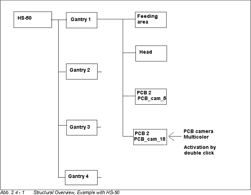
As shown afterwards using the HS-50 for an example, the selected machine (S-25 HM or HS-
50) is displayed graphically, arranged by gantries (1 to 2 or 4), and with the pertinent substruc-
tures (component feeding areas, placement heads, PCB cameras, options, etc.).
User Manual SIPLACE S-25 HM / HS-50 2 PCB Camera Multicolor (Option)
Software Version SC.502.xx 11/00 Issue 2.4 LCU: Configuration PCB Camera Multicolor
45
Å The field "PCB camera Multicolor" is deactivated. Activate the optional PCB camera Multicolor
with a double click on the "LP PC_cam _18", as illustrated above.
Å Do this for all 4 / 2 gantries (HS-50 / S-25 HM).
Å In the menu bar at top, in the Station Editor, select "File" -> "Save" - END".
Å Then select: "File" ->
'DWDPDQDJHU
Å Double click on the ICONs for "Master data".
Å In the window that opens, double click on "Stations".
Å Click once on the "Double click" field that opens and click once on "Translator" to select it and
continue with a double click to select the pertinent station at which the PCB camera Multicolor
is used / was retrofitted.
Å In the "Data manager" window select the field "OK".
All of the windows are closed.
This concludes the work on the line computer for the configuration of the PCB camera Multi-
color. If you have not done so already, carry out the carry out the check "Focus camera / thick-
ness of substrate" as described in Section 2.4.2.
Then carry out the activation / configuration of the PCB camera Multicolor in the SITEST pro-
gram (see Section 2.5).