JUKI FX-3R Maintenance Manual.pdf - 第126页
FX-3R Maintenance Guide 10-4 10-3-2. Operation Key 1) Remo ve two mounting screws c to replace the SAFETY_SWITCH_KEY d . SL6041042TN SEMS cap bolt with washer M4 × 10 SAFETY_SWITCH_KEY Figure 10-3-2-1 Operation Key Rev. …
FX-3R Maintenance Guide
10-3
10-3. Replacing the Cover Open Switch
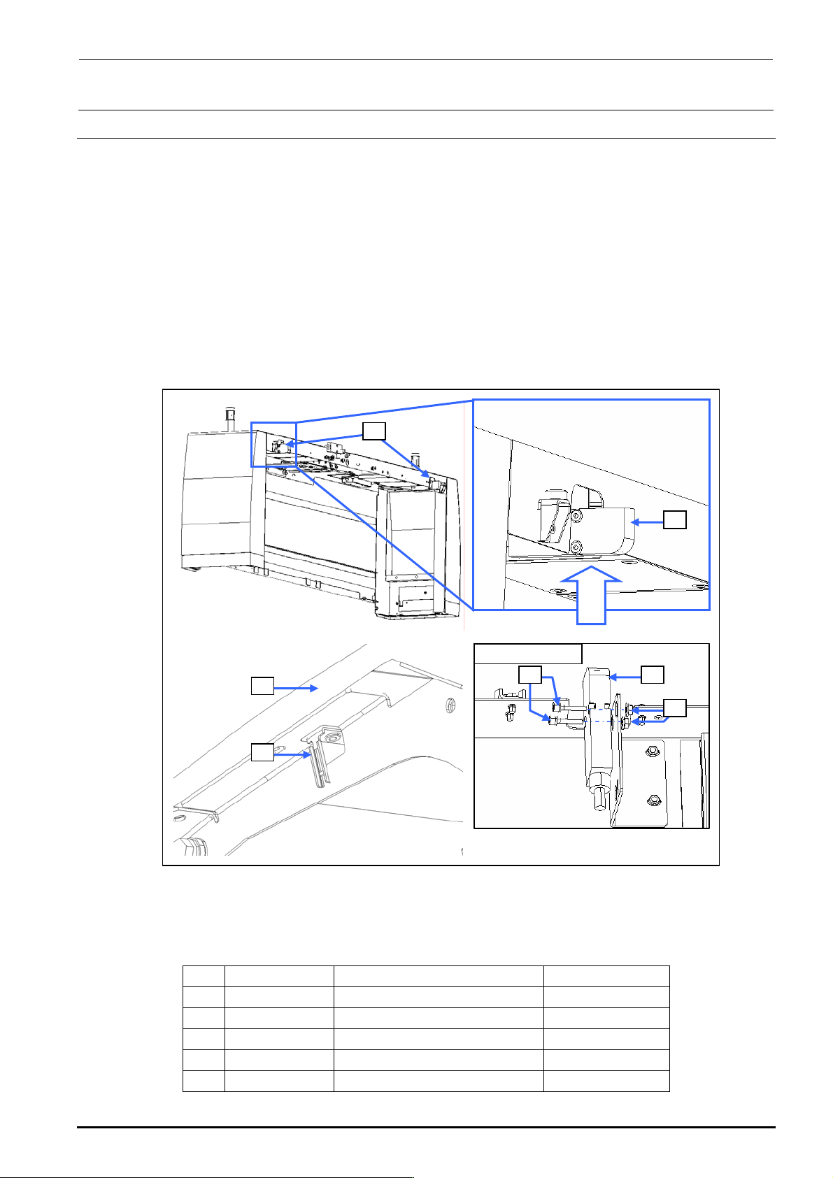
10-3-1. Switch Main Unit
1) Disconnect the connector of the switch c from the relay connector.
2) Cut the tie-up band and remove the set screws d (SL6042042TN) to replace the switch c
main unit.
3) Reassemble the components in the reverse order of disassembly.
After assembling, check to make sure that the assembly has been fit in th e safety cover f, and
the operation key can be inserted into the switch properly.
∗ After the new switch has been mounted, make sure that the safety cover f is mounted
correctly and that the operation key g is inserted into the switch correctly.
Rev. 1.00
Viewed from A
c
c
d c
e
f
g
Viewed
from A
Figure 10-3-1 Replacing the Switch Main Unit
[List of Replacement Parts]
Table 10-3-1 Replacement Parts for Cover Open Switch
No. Part No. Part name Q’ty per machine
c
40002254 COVER_OPEN_SW_CABLE_ASM 8
d
SL6042042TN SEMS cap bolt 16
e
NM3040520SF Nut 16
f
40063507 SAFETY_COVER_FRAME 4
g
HA005280010 SAFTY_SWITCH_KEY 8
FX-3R Maintenance Guide
10-4
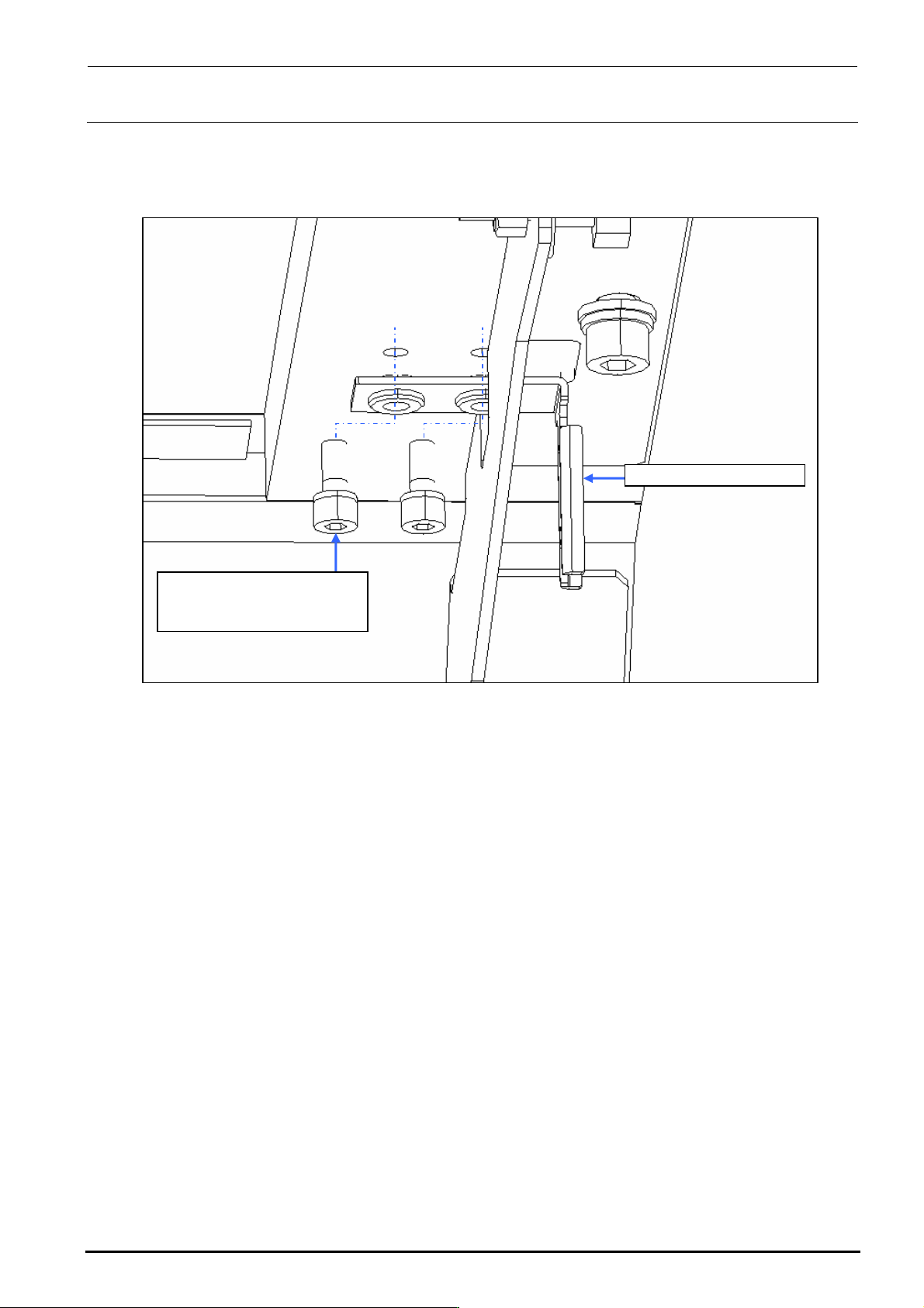
10-3-2. Operation Key
1) Remove two mounting screws c to replace the SAFETY_SWITCH_KEY d.
SL6041042TN
SEMS cap bolt with washer
M4×10
SAFETY_SWITCH_KEY
Figure 10-3-2-1 Operation Key
Rev. 1.00
FX-3R Maintenance Guide
10-5
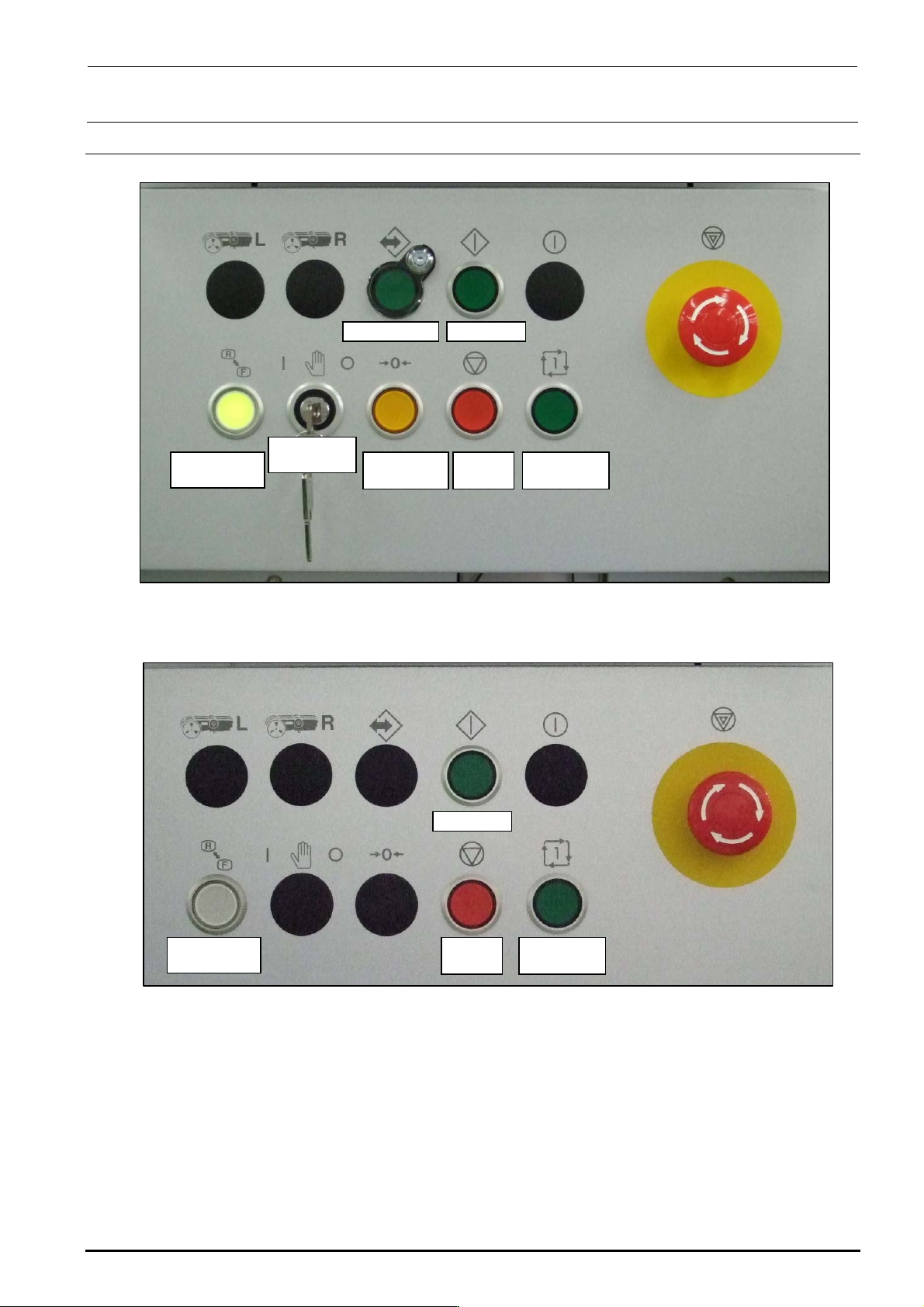
10-4. Replacing the Push-Button Switch (CE Marking Machine)
On-line switch Start switch
Keyboard
setting switch
Origin return
switch
Stop
switch
Single cycle
switch
Maintenance
key switch
Figure 10-4-1 Switch Names on Front Operation Panel
Start switch
Keyboard
setting switch
Stop
switch
Single cycle
switch
Figure 10-4-2 Switch Names on Rear Operation Panel
Rev. 1.00