JUKI FX-3R Maintenance Manual.pdf - 第58页
FX-3R Maintenance Guide 4-7 OCC focus ad just me nt jig 40069017 OCC focus ad just me nt jig Set the light value to a level, at which the vertical lines of the focus adjustment jig can be seen, to adjust the light quanti…
FX-3R Maintenance Guide
4-6
4-5. Adjusting the Focus
<Procedure>
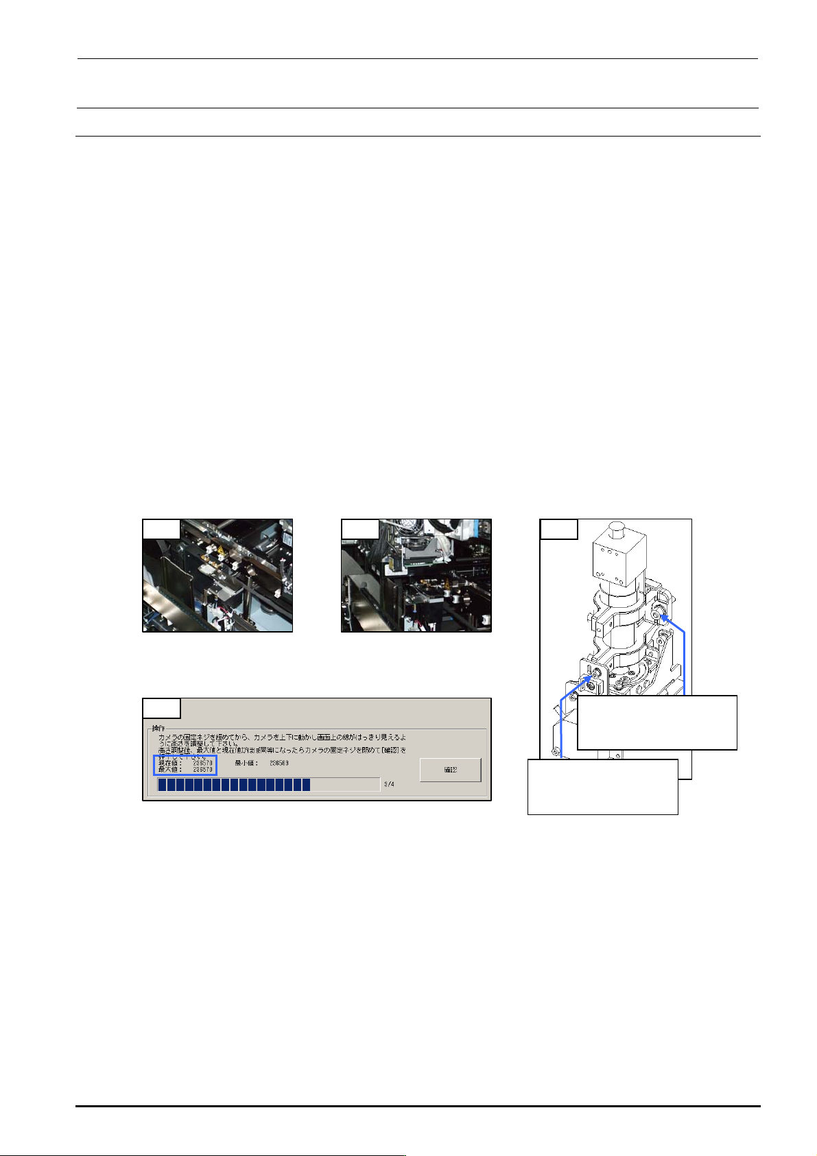
1) Mount the OCC focus adjustment jig on the calibration block.
2) Move the OCC camera to a position above the OCC focus adjustment jig. (Manual
movement)
3) Turn on the light with the standard light selected and start up [MS parameters]-[Check
Adjustment]-[OCC Focus Adjustment]. (See section 5-1. OCC Focus Adjustment, in the MS
parameters.)
4) Loosen the SEMS cap bolts c (×3) and SEMS cap bolt d (×1) of the OCC and gradually
move the OCC up or down.
(Spend about 5 sec. to move from the minimum point to the maximum point or from the
maximum point to the minimum point.)
5) Since the maximum value of the focus status display is determined, adjust the OCC height so
that the maximum value is almost the same as the current value, and then fix the assembly
screws. (If the current value exceeds the maximum value, the maximum value is updated
immediately.)
6) Exit [OCC Focus Adjustment].
1) 2) 4)
c SL6052092TN
SEMS cap bolt with
washer M5×20
d SL6030892TN
SEMS cap bolt with
washer M3×8
5)
Figure 4-5-1
Jig Installation Position
Figure 4-5-2
OCC Focus Adjustment
Position
Figure 4-5-4 MSP (OCC Focus Adjustment)
Figure 4-5-3 Mounting Screws
for Adjustment of
OCC Focus
Rev. 1.00
FX-3R Maintenance Guide
4-7
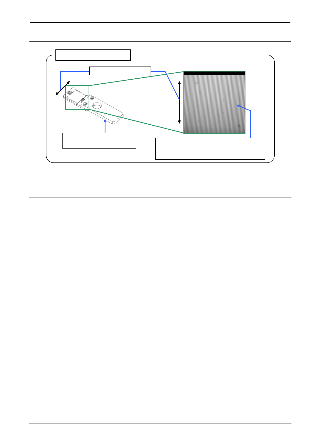
OCC focus ad just ment jig
40069017
OCC focus ad just ment jig
Set the light value to a level, at which the
vertical lines of the focus adjustment jig can
be seen, to adjust the light quantity.
Line drawing direction
Figure 4-5-5 OCC Focus Adjustment Jig
4-6. Adjusting the OCC Light Quantity
<Procedure>
1) Check that the OCC light goes on with manual control.
2) Carry out "Adjustment of OCC Light" in the MS parameters. (See the section related to OCC
light quantity adjustment in the specifications for the MS parameter operation.)
Rev. 1.00
FX-3R Maintenance Guide
4-8
4-7. Replacing the Solder Recognition Light Board
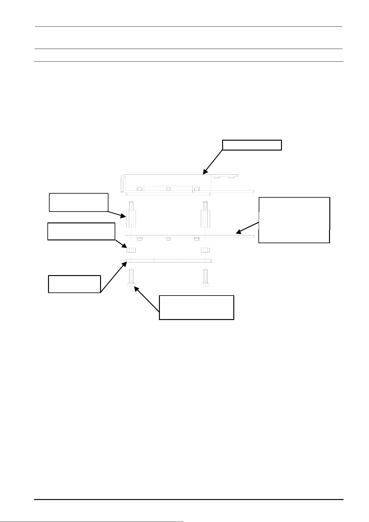
<Procedure>
1) Remove the brazier head screws to detach the PRISM BASE, OCC angle light board, and
board spacers.
2) Reassemble the components in the reverse order of disassembly.
3) After the solder recognition light has been replaced, adjust the OCC light. (See 4-8, List of
Readjustment Items after Replacement.)
HX00335000G
基板スペーサ :4個
角度照明ユニット
HX00354000D
基板スタッド :4個
40032433
低頭ねじ M3×10 :4個
40014043
PRISM BASE
40047508
OCC A LIGHT PCB ASM
取付け向きに注意
(LED面下向き)
Angle light unit
Board stud: 4 pcs.
Board spacer: 4 pcs.
Carefully check t he
mounting orientation.
(LED surface face s
downward.)
Brazier head screw
M3 × 10: 4 pcs.
Rev. 1.00