00194340-01.pdf - 第25页
Retrofit Instructions & User’s Manual / Automatic Vacuum Support Pins (AVSP) Edition 04/2006 2.4.2 Electrical installation → Open the cover on top of conveyor’s conversion card. → Loosen the hexagon pillar on conveyo…
Retrofit Instructions & User’s Manual / Automatic Vacuum Support Pins (AVSP)
Edition 04/2006
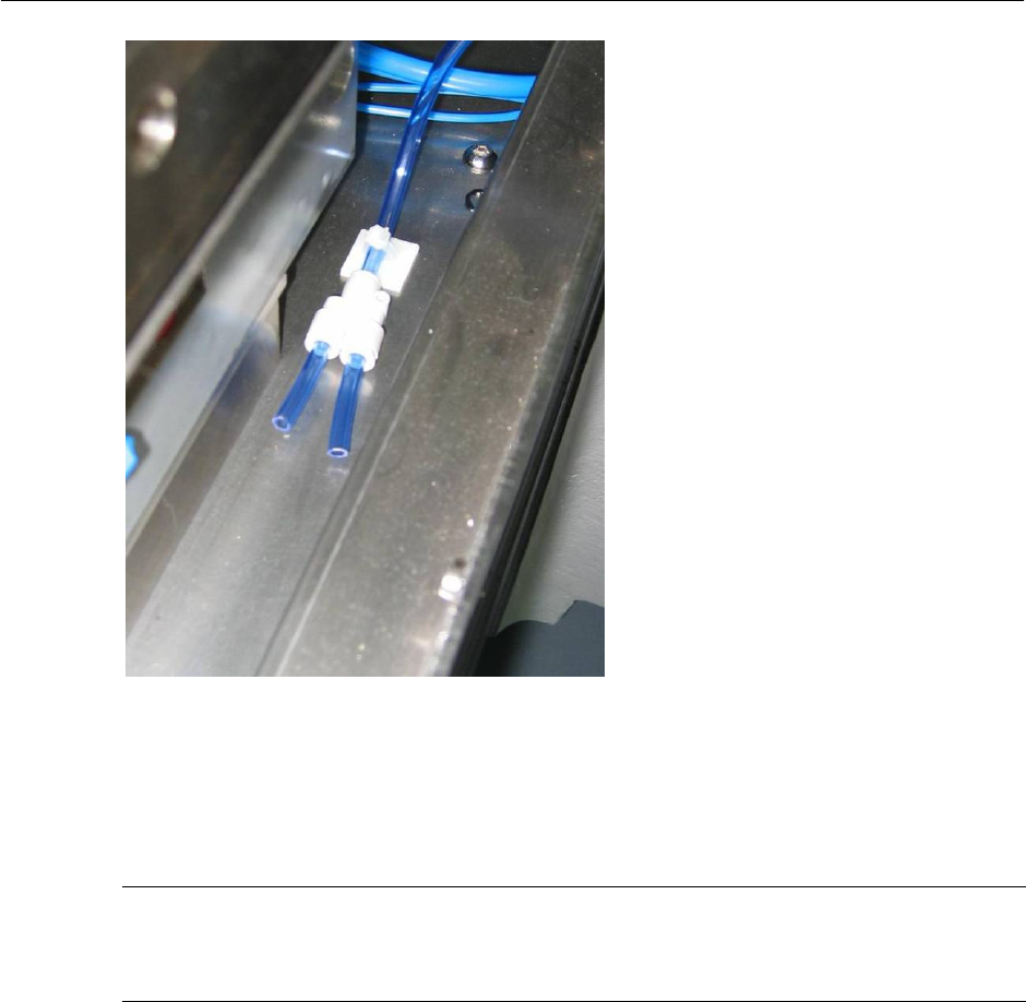
Figure 2.4.1-9 Y-Union at the end of line
→ Place the control unit with respect to placement areas at location shown in Figure 2.4.1-8
and connect tubing (Item No.: 03031604-FS) from Y-Union to control unit.
NOTE
Layout shown in Figure 2.4.1-8 applies to Single Conveyor machine as well. User can skip
tubing laying on placement area 3 & 4.
2-20
Retrofit Instructions & User’s Manual / Automatic Vacuum Support Pins (AVSP)
Edition 04/2006
2.4.2 Electrical installation
→ Open the cover on top of conveyor’s conversion card.
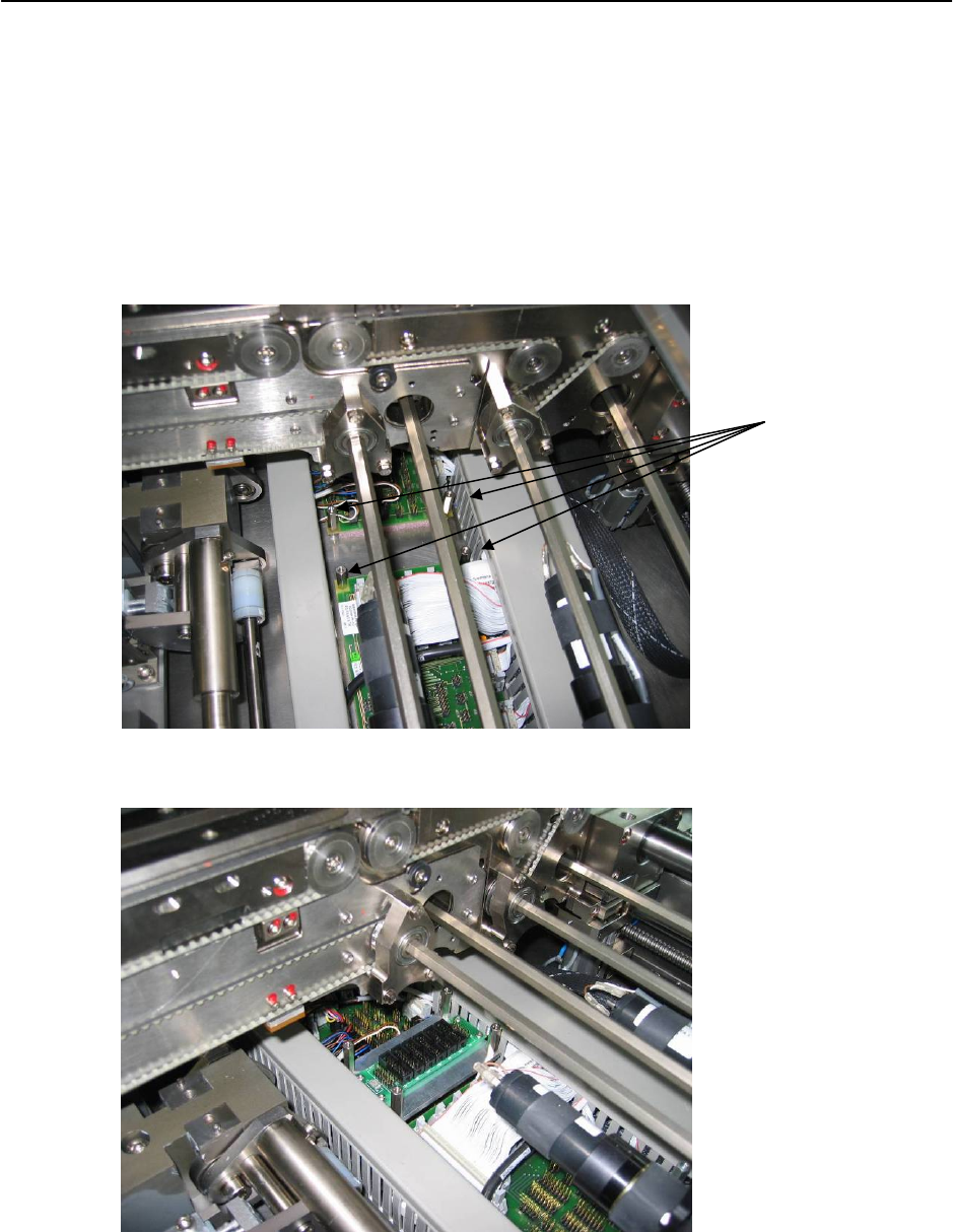
→ Loosen the hexagon pillar on conveyor’s conversion board. Replace it with I/O Card
Assembly (Item No.: 03031464-FS) provided.
Replace with I/O
Card Assembly
(shorter hexagon
pillar at the
bottom)
Figure 2.4.2-1 Replacing hexagon pillar with I/O Card Assembly
Figure 2.4.2-2 Fix I/O card assembly
2-21
Retrofit Instructions & User’s Manual / Automatic Vacuum Support Pins (AVSP)
Edition 04/2006
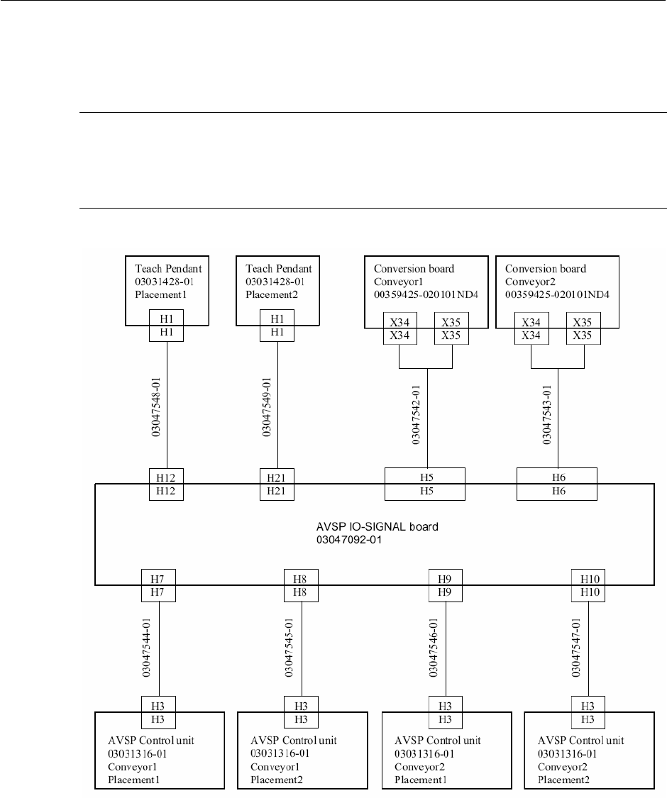
→ Connect all cables from I/O board as according to drawing in Figure 2.4.2-3 except the 2
cables to teach pendant. Lay cables as shown in Figure 2.4.2-4.
NOTE
I/O board is designed to accommodate 4 placement areas. However, if AVSP is not
necessary at all placement areas, laying of cables can be skipped at the unused areas (E.g.
Single conveyor). This will not affect the operation of used area.
Figure 2.4.2-3 Cable connection drawing
2-22