00194340-01.pdf - 第31页
Retrofit Instructions & User’s Manual / Automatic Vacuum Support Pins (AVSP) Edition 04/2006 → Connect 3 tubing from distributor assembly (Item No.: 03040773 -FS for dual conveyor, 03040851-FS for single conveyor) to…
Retrofit Instructions & User’s Manual / Automatic Vacuum Support Pins (AVSP)
Edition 04/2006
2.4.4 Air distributor installation
→ Loosen cover plate for PCB to ease installation.
NOTE
It is recommended that user to adjust the conveyor width to maximum or minimum as to
allow more space during installation.
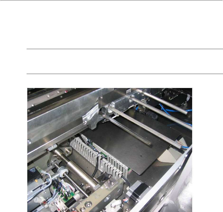
Figure 2.4.4-1 Air interface tubing to pin module
2-26
Retrofit Instructions & User’s Manual / Automatic Vacuum Support Pins (AVSP)
Edition 04/2006
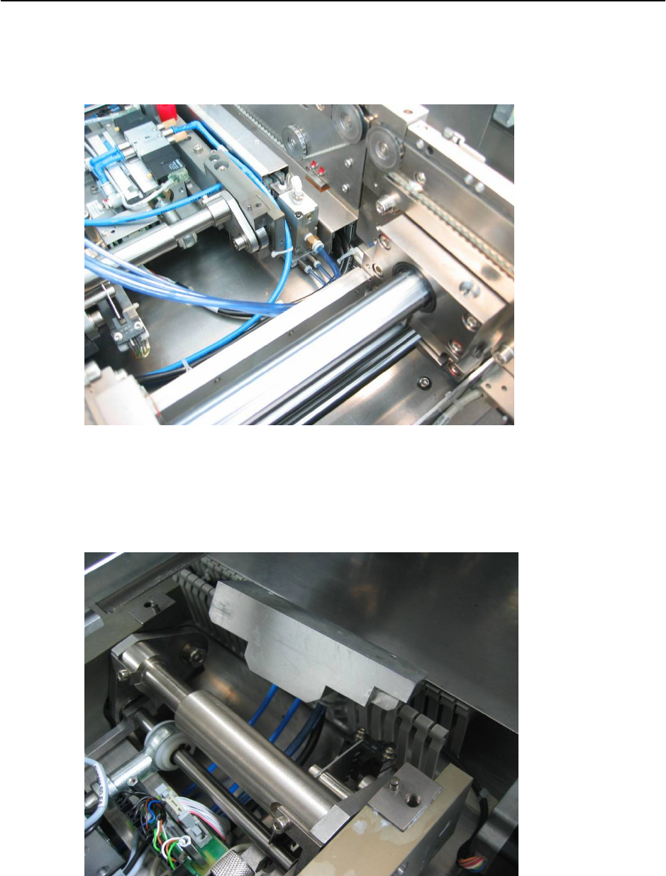
→ Connect 3 tubing from distributor assembly (Item No.: 03040773-FS for dual conveyor,
03040851-FS for single conveyor) to control unit and lay the tubes under lifting table as
shown in Figure 2.4.4-2.
Figure 2.4.4-2 Air interface tubing from control unit to distributor
→ Connect the 3 tubes coming out from lifting table’s bottom to distributor assembly. Follow
by mounting the distributor to AVSP option lifting table top plate (Item No.: 03046506-FS
for single conveyor, 03047412-FS for dual conveyor).
Figure 2.4.4-3 Air interface tubing from control unit to distributor
2-27
Retrofit Instructions & User’s Manual / Automatic Vacuum Support Pins (AVSP)
Edition 04/2006
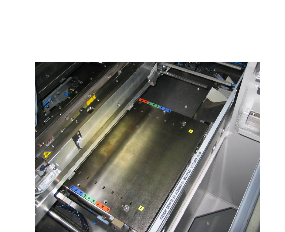
→ Mount the option plate on lifting table. Mounted option plate as shown in Figure 2.4.4-4.
→ Continue to assemble distributor on any other placement areas where AVSP is required.
→ Mount all dismounted lifting table top plate and PCB cover to its original location.
Figure 2.4.4-4 Mounted option plate
2-28