00194340-01.pdf - 第29页
Retrofit Instructions & User’s Manual / Automatic Vacuum Support Pins (AVSP) Edition 04/2006 Figure 2.4.3-2 Pendant’s cable layout for dual conveyor HF-Se ries 2-25
Retrofit Instructions & User’s Manual / Automatic Vacuum Support Pins (AVSP)
Edition 04/2006
2.4.3 Teach pendant installation
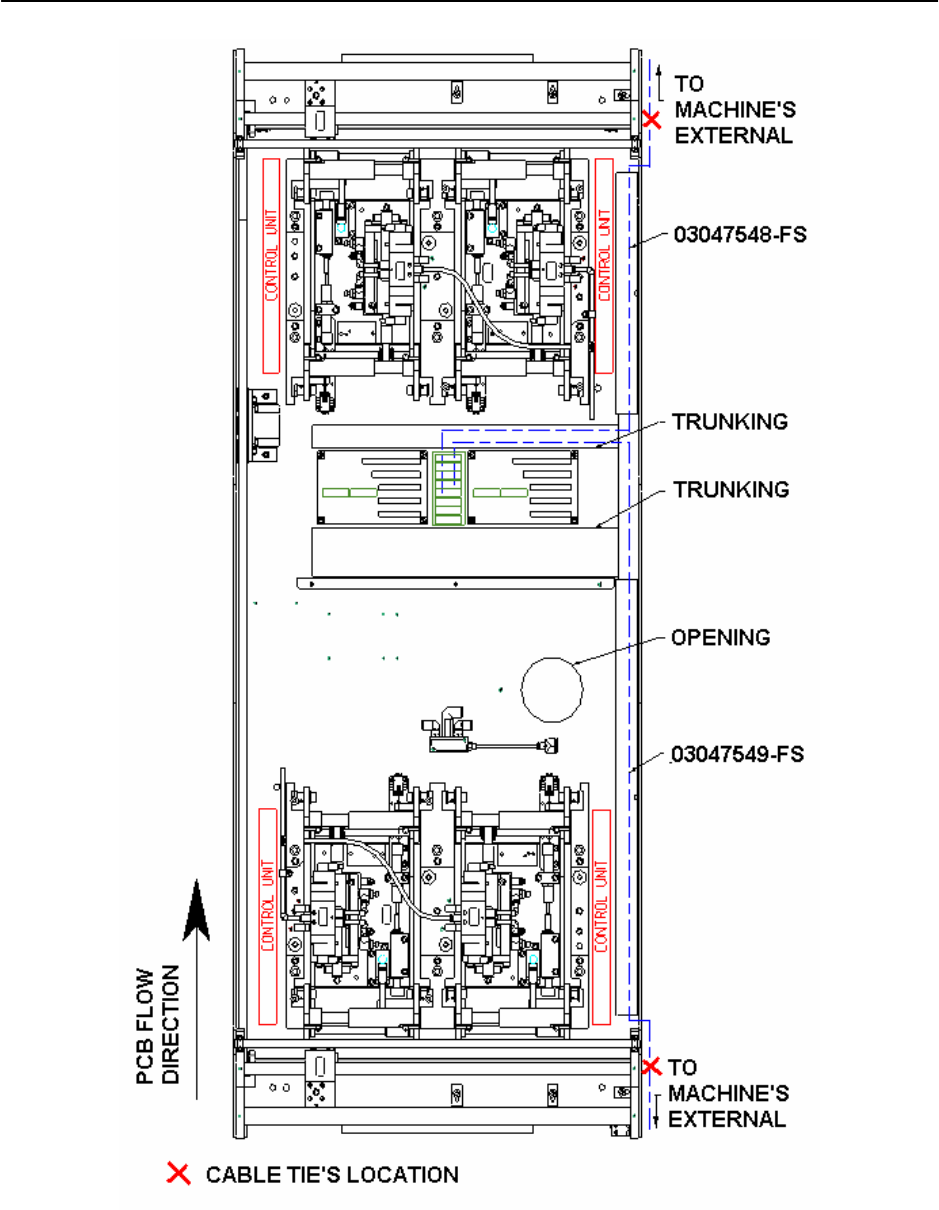
→ Connect pendant’s cable to I/O board and lay the cables as according to Figure 2.4.3-2.
Tie up cablings together with the cable tie (Item No.: 00805140-FS) and bases (Item No.:
00318666-FS) provided.
NOTE
I/O board is designed to accommodate 2 teach pendants that controls AVSP on 4 placement
areas. However, if AVSP is not necessary at all placement areas, laying of cables can be
skipped at the unused areas. This will not affect the operation of used area.
→ Following then, lay the end of pendant’s cable out of the machine thru the opening on
machine’s frame.
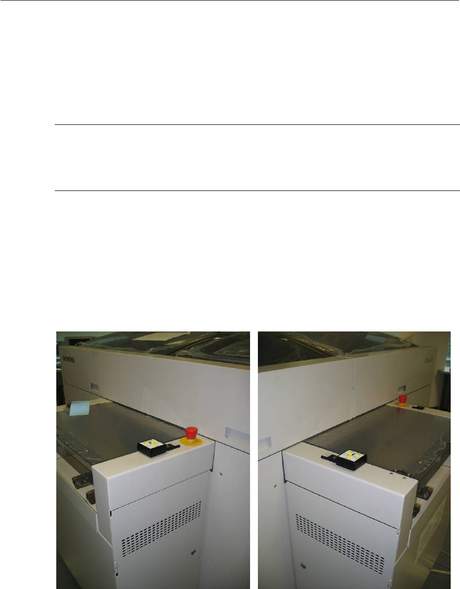
→ Fix the teach pendant at location shown and connect it to cable.
→ Repeat similar steps for another teach pendant if necessary.
→ Reassemble all the covers and trunking. Reassemble all lifting table’s top plate &
component table.
Figure 2.4.3-1 Pendant’s location for placement 1 & 4 (Left), 2 & 3 (Right)
2-24
Retrofit Instructions & User’s Manual / Automatic Vacuum Support Pins (AVSP)
Edition 04/2006
Figure 2.4.3-2 Pendant’s cable layout for dual conveyor HF-Series
2-25
Retrofit Instructions & User’s Manual / Automatic Vacuum Support Pins (AVSP)
Edition 04/2006
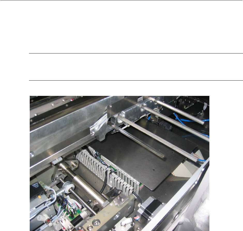
2.4.4 Air distributor installation
→ Loosen cover plate for PCB to ease installation.
NOTE
It is recommended that user to adjust the conveyor width to maximum or minimum as to
allow more space during installation.
Figure 2.4.4-1 Air interface tubing to pin module
2-26