00197543-01_SM_JTF-S_ JTF-M_en.pdf - 第70页
Service Works Troubleshooting SIPLACE JTF-S 2.8.3 Checking the Indicator LEDs on the Solenoid Bank (SIPLACE JT F-S) 70 Service Manual SIPLACE JEDEC Tray Feeder 2.8.3 2 . 8 . 3 C h e c k in g t h e I n d ic a t o r L E D …
Service Works
2.8.2 Input and Sensor Status on Control Board (SIPLACE JTF-S) Troubleshooting SIPLACE JTF-S
Service Manual SIPLACE JEDEC Tray Feeder 69
2.8.2
2.8.2 Input and Sensor Status on Control Board (SIPLACE JTF-S)
Input and Sensor Status on Control Board (SIPLACE JTF-S)
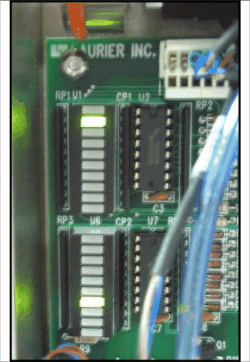
This is a list of the functions indicated by the LEDs input banks U1 and U6:
These LED status can be very helpful when trouble shoot any sensor or communication issues.
Location Function:
▪ U1-1 Lift cylinder up
▪ U1-2 Lift cylinder down
▪ U1-3 Forward slow
▪ U1-4 Stop at end
▪ U1-5 Tray position
▪ U1-6 Reset
▪ U1-7 Stop switch
▪ U1-8 Spare
▪ U1-9 Input 1
▪ U1-10 Input 2
▪ U6-1 Inhibit switch
▪ U6-2 Elevator down
▪ U6-3 Stack full
▪ U6-4 Stop at stack
▪ U6-5 Reverse slow
▪ U6-6 Elevator high
▪ U6-7 Elevator low
▪ U6-8 Door
▪ U6-9 Manual index
▪ U6-10 Host index
▪ U12-4 Full / Empty LED (blue) constant on= Input
stack is empty / Flashing = Output stack is full
▪ U12-5 Inhibit LED (yellow) constant on= Inhibit condi-
tion / Flashing = Inhibit condition, elevator moving up.
▪ U12-6 Stop/Error LED (orange) constant on= Feeder
stopped / Flashing = Error condition
Service Works
Troubleshooting SIPLACE JTF-S 2.8.3 Checking the Indicator LEDs on the Solenoid Bank (SIPLACE JTF-S)
70 Service Manual SIPLACE JEDEC Tray Feeder
2.8.3
2.8.3 Checking the Indicator LEDs on the Solenoid Bank (SIPLACE JTF-S)
Checking the Indicator LEDs on the Solenoid Bank (SIPLACE JTF-S)
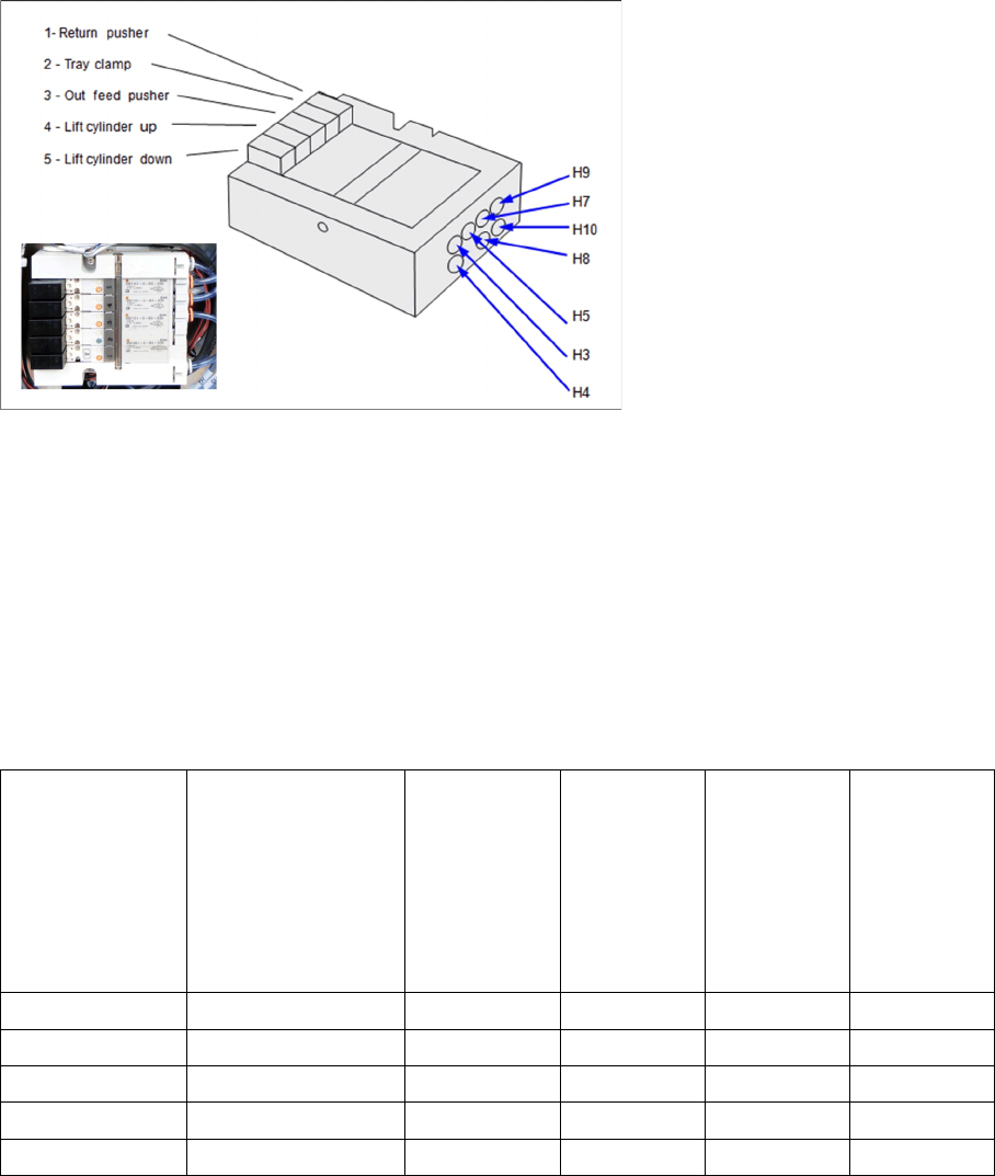
The feeder includes a bank of at least fi ve solenoids that control the pneumatic functions (see figure "
Indicator LEDs on Solenoids and Pneumatic Tube Connection"). Each solenoid includes an LED that
lights when that solenoid is active. These can also be helpful as you troubleshoot the feeder.
Indicator LEDs on Solenoids and Pneumatic Tube Connection
2.8.4
2.8.4 Start-Functions and Error Conditions to SIPLACE (SIPLACE JTF-S)
Start-Functions and Error Conditions to SIPLACE (SIPLACE JTF-S)
Different versions of the feeder behave differently on start-up. This depends mainly on the communica-
tions mode and firmware version (see "2.8.5 Troubleshooting Charts SIPLACE JTF-S" [ ➙ 71]
There are two points where the start-up functions may be different:
▪ Power-up and initialization
▪ First index
In order to troubleshoot a feeder, you need to understand these differences. Begin by referring to "2.8.5
Troubleshooting Charts SIPLACE JTF-S" [ ➙ 71] to identify the communications mode. Next, check the
table below to identify the start-up functions for the unit you are working on.
Error Conditions Reported to Host Machine
In the current version of the feeder, there is only one output signal or line for Error. However, there could
be eight separate conditions that might trigger the Error output. If the feeder reports an Error to the host,
the cause could be any of the following:
On power-up, manu-
al initialization is re-
quired. Set conveyor
speed manually. (El-
ev button for fast- or
the two Index Buttons
together for slow
speed).
On power- up,
feeder initializ-
es automati-
cally.
After initiali-
zation, tray
elevator au-
tomatically
moves up.
Feeder auto-
matically in-
dexes fi rst
tray.
Feeder stops
and waits for
index signal
for host.
Simple x x x
Intermediate x x x
Advanced x x x
Siemens x x x
Fuji x x x

Service Works
2.8.5 Troubleshooting Charts SIPLACE JTF-S Troubleshooting SIPLACE JTF-S
Service Manual SIPLACE JEDEC Tray Feeder 71
2.8.5
2.8.5 Troubleshooting Charts SIPLACE JTF-S
Troubleshooting Charts SIPLACE JTF-S
2.8.5.1
2.8.5.1 General Problems
General Problems
To recover from an exchange error:
► Identify the cause of the error, warped or clamped trays.
► Check the blinking pattern on the orange LED and compare with the list below and the troubleshoot-
ing chart.
► Correct the problem (in most cases this means remove the tray from the conveyor).
► Press the Stop button followed by the Reset button.
⇨ The orange LED should stop fl ashing. If it does not, repeat the first three steps. If the error persists,
continue trouble shooting using the charts on next pages. If error still there, contact vendor.
⇨ When the orange LED stops fl ashing, the feeder is ready to resume normal operation.
STOP ERROR SYMPTOME ACTION NEEDED
FAILED TO RECLAMP Re-clamp failed during initializa-
tion or reset. Stop button pushed.
► Press Reset to continue.
TRAY IN STACK Tray exchange was initiated ► Remove the tray from the
"stop at stack" sensor.
LIFT NOT DOWN with a tray partially in the stack. ► Check for a jammed tray or
other obstacle.
► Press Reset to continue.
TRAY NOT CLEAR The tray lift mechanism did not
go down all of the way.
► Check for a jammed tray or
other obstacle.
► Press Reset to continue.
TRAY NOT IN The tray returning from the pick
position did not clear the "return
slow-down" sensor.
► Check for a jammed tray or
other obstacle.
► Press Reset to continue.
LIFT NOT UP The tray returning from the pick
position did not reach the "stop at
stack" sensor.
► Check for a jammed tray or
other obstacle.
► Press Reset to continue.
TRAY NOT FED The tray lift mechanism did not
come up all of the way.
► Check for a jammed tray or
other obstacle.
► Press Reset to continue.
TRAY NOT AT END The tray being conveyed to the
pick position did not reach the
"forward slow-down" sensor.
► Check for a jammed tray or
other obstacle.
► Press Reset to continue.
Error Code Name Blink Pattern Description
1 DOOR_IS_OPEN . . . _ Elevator door is open.
2 FULL_ERROR . . _ . The output stack is full of
trays.
3 STOP_ERROR . . _ _ Stop button pushed.
4 FAILED_TO_RECLAMP . _ . . Re-clamp during initiali-
zation or reset failed.
5 TRAY_IN_STACK . _ . _ Tray Exchange initiated
w/ tray partially in stack.