Service Manual HS60.pdf - 第36页
2 O per ati onal sa fety S er vice Ma nual H S- 60 2.3 Las er clas sifi cat ion 03/ 200 3 U S Iss ue 34 2.3. 5 Safety in struction s for do cking an d undock ing the co mponent trolle y . F ig. 2. 3 - 2 S afe ty in str u…
Service Manual HS-60 2 Operational safety
03/2003 US Issue 2.3 Laser classification
33
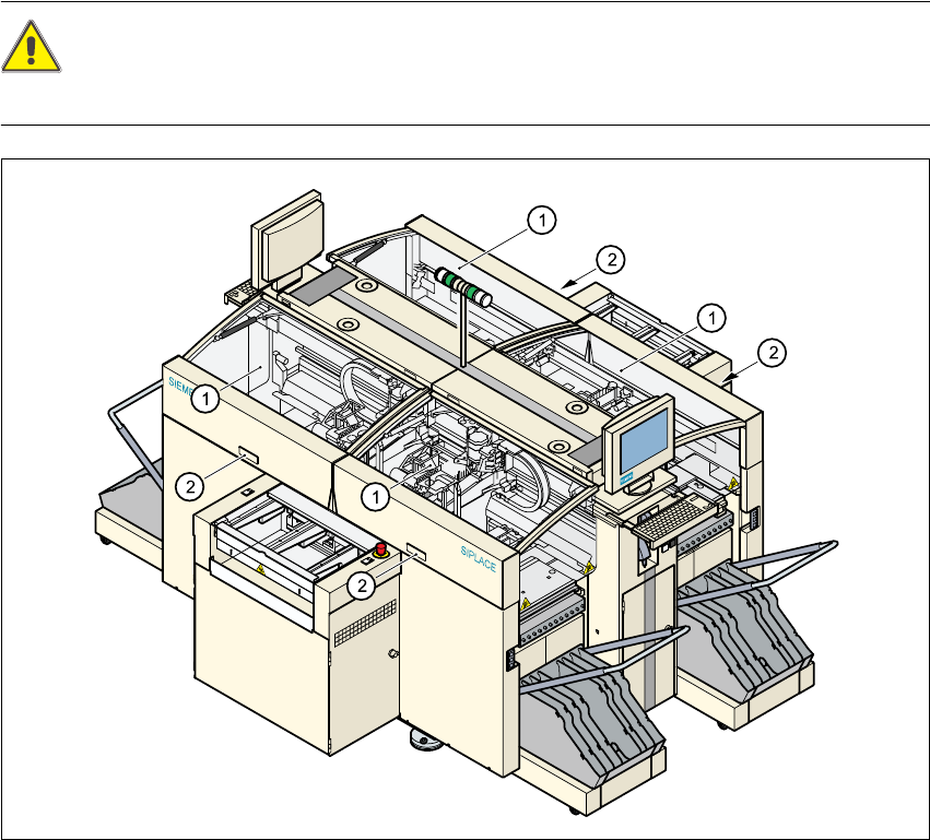
2.3.4 Safety instructions for closing the protective covers
To prevent any risk of injury when the protective covers on automatic placement machines are
closed, the owner must instruct his operators to use the protective covers exactly as specified in
the following instructions. 2
CAUTION RISK OF CRUSHING HANDS 2
IF THE PROTECTIVE COVERS AREOPENEDOR CLOSEDI NCORRECTLY
Fig. 2.3 - 1 Safety instructions for closing the protective covers
(1) Protective covers
(2) Recessed grips
Æ When opening or closing the protective covers, always hold the covers by the recessed grips.
If the shock absorbing capacity of the protective covers reduces over time, for example, your
hands can easily be crushed if you do not close the covers using the recessed grips.
2 Operational safety Service Manual HS-60
2.3 Laser classification 03/2003 US Issue
34
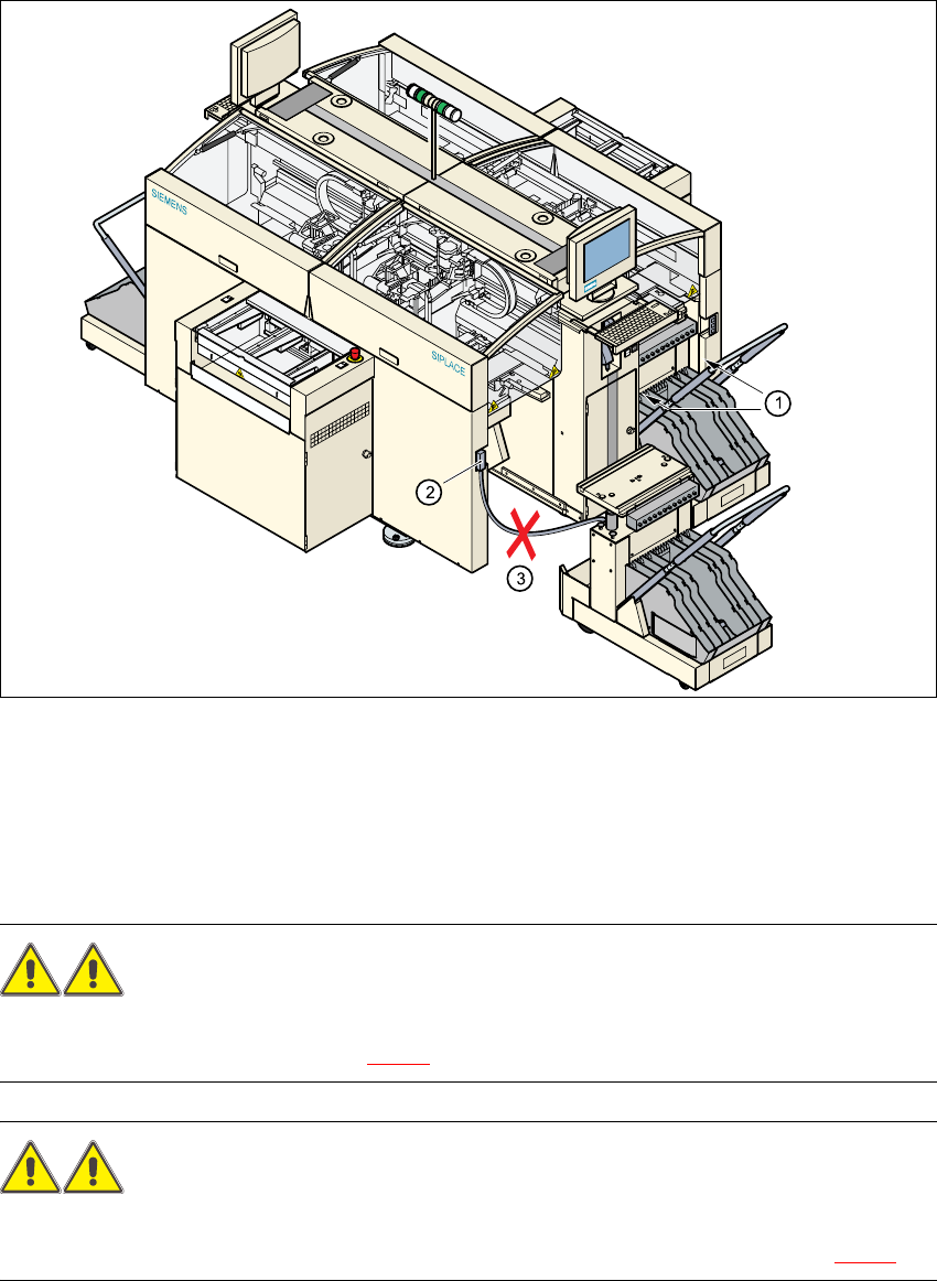
2.3.5 Safety instructions for docking and undocking the component trolley
.
Fig. 2.3 - 2 Safety instructions on the component trolley
WARNING 2
Never reach into the gaps between the component trolley and the placement system frame while
the machine is running (item 1 in Fig. 2.3 - 2).
WARNING 2
The power cable for the component trolley must not be connected to the machine socket, or
pulled out of it, unless the component trolley is docked on the machine (Pos. 2 in Fig. 2.3 - 2).
(1) Vertical gap between the placement system frame and the component trolley
(2) Plug for connecting the component trolley cable
(3) Connecting cable for compressed air and main power supply to the component trolley
Service Manual HS-60 2 Operational safety
03/2003 US Issue 2.3 Laser classification
35
WARNING 2
Never connect the connecting cable for the component trolley to the socket on the placement
system and then operate the component trolley outside the machine via the compressed air con-
trol unit (item 3 in Fig. 2.3 - 2)
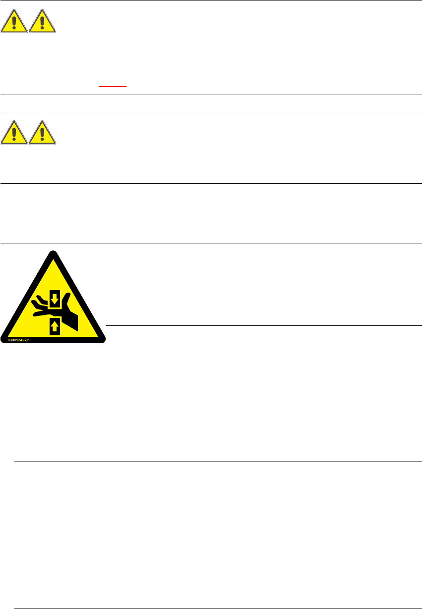
WARNING DANGER OF CRUSHING
You must always take hold of the bar with both hands whenever you want to move the component
trolley into the machine. 2
2.3.6 Safety instructions for changing the table height of component trolleys
WARNING RISK OF CRUSING CRUSHING
The component trolley must only be converted to modify the default ta-
ble height by trained Service personnel.
Act with considerable care during the conversion process since the sys-
tem contains large weights or compression springs (potential energy).2
Converting the component trolley to suit a different line height 2
Æ Use the placement system’s pneumatic controller to raise the table bed. Then insert a 120mm
spacer block between the table bed and crossbeam, and lower the bed onto the block.
Æ Dismantle the internal paneling.
Æ Swivel the handle down. The latching disk swivels down as well.
Æ Set the screw to the desired dimension and lock in place with the locknut.
PLEASE NOTE:
If you cannot loosen the adjusting screw far enough, the crossbeam must be raised. 2
Æ Fix the lifting device to the crossbeam.
Æ Carefully open the crossbeam clamp.
Æ Raise the crossbeam until the end of the tube projects approx. 1mm out of the clamp.
Æ Tighten the crossbeam clamp.
Æ Then turn the adjusting screw to the desired dimension and lock in place with the locknut.