Service Manual HS60.pdf - 第45页
Se rv ice M a nu al HS-6 0 2 Ope rati on al saf et y 03/ 200 3 U S Iss ue 2.4 Safe ty eq uipme nt 43 2.4. 3.2 Position of E MERGENCY -STOP mushroom-head push-button, c ircuit brea ke r s etc. on the ma chi ne 2 Fig. 2.4 …
2 Operational safety Service Manual HS-60
2.4 Safety equipment 03/2003 US Issue
42
2.4.3 Main power switch, EMERGENCY-STOP mushroom-head push-button,
protective cover switch
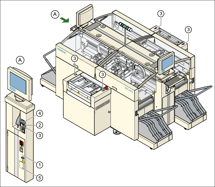
2.4.3.1 Position of the main power switch, start buttons etc. on the machine
2
Fig. 2.4 - 4 Position of main switch, start buttons etc.
(1) Main power switch
(2) Stop button (black)
(3) Start button (white)
(4) Component counter
(5) Service socket in the power supply unit behind the safety door
2
Service Manual HS-60 2 Operational safety
03/2003 US Issue 2.4 Safety equipment
43
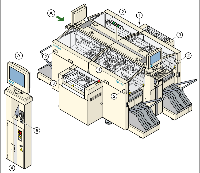
2.4.3.2 Position of EMERGENCY-STOP mushroom-head push-button, circuit
breakers etc. on the machine
2
Fig. 2.4 - 5 EMERGENCY-STOP mushroom-head push-button, circuit-breaker
(1) EMERGENCY-STOP mushroom-head push-button
(2) Protective cover switch
(3) Cover switches over the PCB conveyors
(4) Protective contactor combination in the power supply unit behind the safety door
(5) Key switch
2
key switch open: position 0 for normal operation
key switch closed: position I for service purposes
2 Operational safety Service Manual HS-60
2.4 Safety equipment 03/2003 US Issue
44
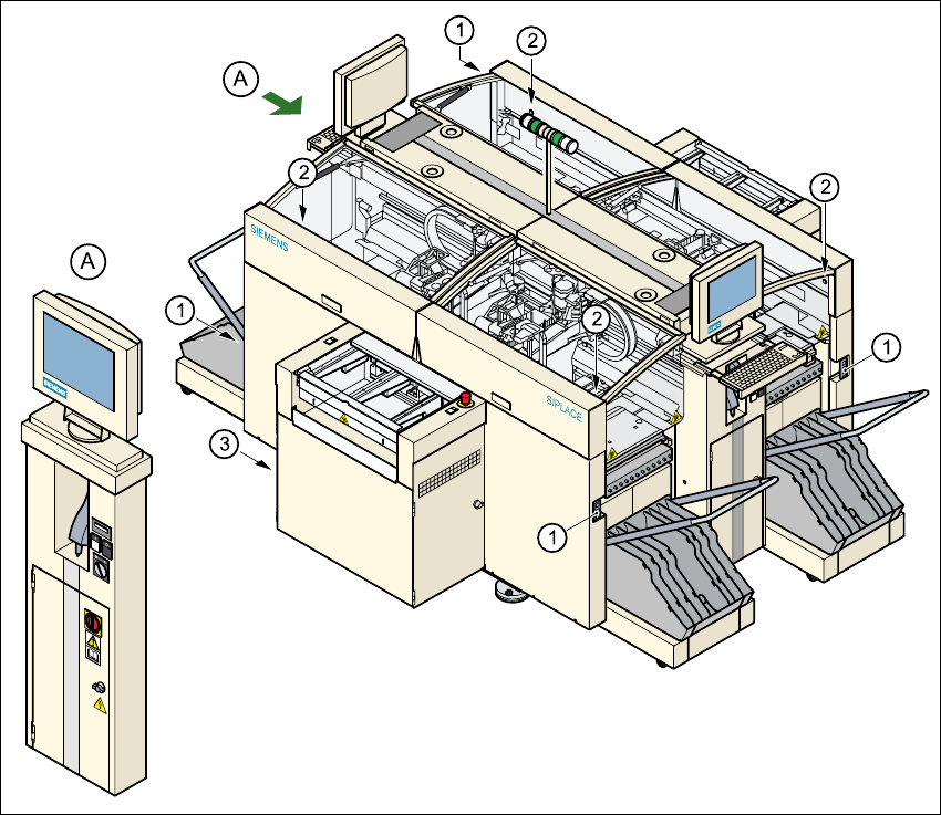
2.4.3.3 Position of UPS, station computer and sockets for connecting the CO trolleys
2
Fig. 2.4 - 6 UPS, station computer, sockets for connecting the CO-trolley
(1) Socket for connecting the CO trolley
(2) Push-button for raising the component trolley, with the cover flap over it
(3) UPS and station computer