Service Manual HS60.pdf - 第91页
HS -60 Se rvic e Manu al 3 P owe r Su pply 03/ 200 3 U S Iss ue 3.9 Repl acin g par ts 89 3 Fig. 3.9 - 1 M8 he xago n socke t-hea d screw for f ixing th e uni ts 3.9. 3 What to do on com pletion o f the s ervicing wo rk …

3 Power Supply HS-60 Service Manual
3.9 Replacing parts 03/2003 US Issue
88
3.9 Replacing parts
3.9.1 Safety instructions
DANGER The placement system is supplied with 3 x 400 VAC (or 3 x 204
VAC / 3 x 230 VAC / 3 x 380 VAC / 3 x 415 VAC) ± 5 %, 50/60 Hz main power voltage. 3
– Consequently, parts of the system carry potentially lethal voltages, even when switched off at
the main switch.
– Incorrect handling of the placement system can therefore result in death or severe injury or
considerable damage to equipment.
– Measurements and repairs must always be carried out by appropriately qualified personnel.
– Always follow the safety instructions in chapter 2 of this manual.
– Always follow the applicable accident prevention and VDE regulations (particularly DIN EN 60
204 part 1) or the regulations specific to your country.
– Before starting any repairs, switch off at the main switch and disconnect the placement system
from the main power supply.
– Secure the system to prevent it being switched on again. If these instructions are not followed,
it is possible to touch live parts, which could result in death or severe injury.
3.9.2 Preparing the power supply unit for replacing parts
Æ End all placement operations on the placement system.
Æ Shut down the Windows NT operating system correctly, otherwise problems may occur when
restarting or data may be lost.
Æ Switch the placement system off at the main switch.
Æ Disconnect the placement system from the main power supply.
Æ Secure the placement system to prevent it being switched on again and put up a sign to indi-
cate that servicing work is being carried out (see chapter 2, Operational safety).
Æ Open the safety doors with the double-bit key.
Æ Loosen the M8 hexagon socket-head screw fixing the unit to the underside of the front panel
(see Fig. 3.9 - 1
on page 89).
HS-60 Service Manual 3 Power Supply
03/2003 US Issue 3.9 Replacing parts
89
3
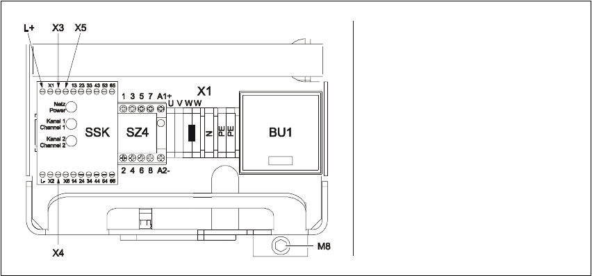
Fig. 3.9 - 1 M8 hexagon socket-head screw for fixing the units
3.9.3 What to do on completion of the servicing work
Æ Fit the power supply unit and fix in place with the M8 hexagon socket-head screw
Æ Make sure that you do not squash the cable when inserting the board
Æ Lock the safety doors
Æ Remove the key and keep in a safe place
3
3
Ziehen Sie den Einschub
vorsichtig heraus
A
chten Sie darauf, dass die
Kabel nicht gequetscht werden
Beschädigen Sie Isolierung
nicht
3 Power Supply HS-60 Service Manual
3.9 Replacing parts 03/2003 US Issue
90