Service Manual HS60.pdf - 第46页
2 O per ati onal sa fety S er vice Ma nual H S- 60 2.4 S afe ty equi pment 03/ 200 3 U S Iss ue 44 2.4. 3.3 Position of UPS, st ation computer a nd socket s for c onnecting the CO trolle ys 2 F ig. 2. 4 - 6 UP S , s tat …
Service Manual HS-60 2 Operational safety
03/2003 US Issue 2.4 Safety equipment
43
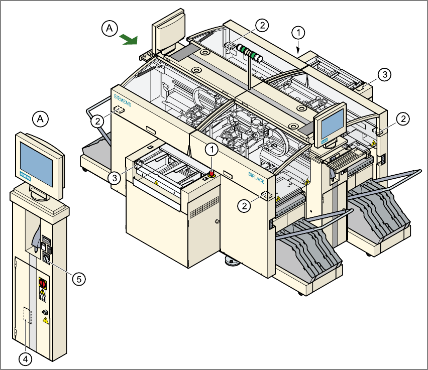
2.4.3.2 Position of EMERGENCY-STOP mushroom-head push-button, circuit
breakers etc. on the machine
2
Fig. 2.4 - 5 EMERGENCY-STOP mushroom-head push-button, circuit-breaker
(1) EMERGENCY-STOP mushroom-head push-button
(2) Protective cover switch
(3) Cover switches over the PCB conveyors
(4) Protective contactor combination in the power supply unit behind the safety door
(5) Key switch
2
key switch open: position 0 for normal operation
key switch closed: position I for service purposes
2 Operational safety Service Manual HS-60
2.4 Safety equipment 03/2003 US Issue
44
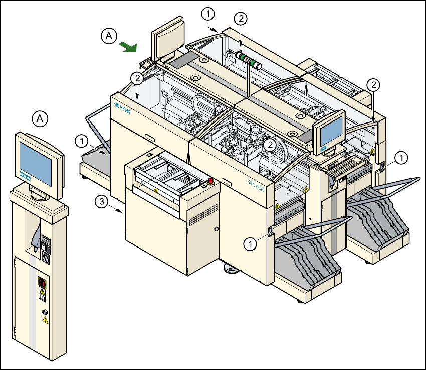
2.4.3.3 Position of UPS, station computer and sockets for connecting the CO trolleys
2
Fig. 2.4 - 6 UPS, station computer, sockets for connecting the CO-trolley
(1) Socket for connecting the CO trolley
(2) Push-button for raising the component trolley, with the cover flap over it
(3) UPS and station computer

Service Manual HS-60 2 Operational safety
03/2003 US Issue 2.4 Safety equipment
45
2.4.3.4 Description of the functions
Main power switch in the OFF position (see item 1 in Fig. 2.4 - 4) 2
The main power switch disconnects the three phases L1, L2, and L3 from the power supply. 2
WARNING 2
The following components still carry potentially lethal voltages even if the main power switch is
switched off: 2
– cable connection terminals 1, 3, and 5 of the S1 main power switch
– main power filter Z1
– BU1 service socket
– F1 automatic circuit breaker for the service socket
– The color of all individual wires, which still carry potentially lethal voltages even if the main
power switch is switched off, is brown.
– The uninterruptible power supply and the station computer may also still carry potentially lethal
voltages when the main power switch is switched off.
Æ Death, serious injury or considerable damage may result if these automatic placement sys-
tems are handled incorrectly.
Æ Always follow the applicable accident prevention and DIN regulations (particularly DIN EN 60
204, part 1) and the applicable regulations in your own country.
Æ The safety door to the power supply must ONLY be opened by appropriately qualified and
trained personnel.
Main power switch in the ON position 2
After switching on the main power switch, the station computer and the machine controller will
start. All supply voltages, apart from the link voltages for the gantry axes (200 V) and the star axes
(100 V) are then available. 2
Stop button, black (item 2 in Fig. 2.4 - 4) 2
These buttons are used to stop the placement system. 2
Start button, white (item 3 in Fig. 2.4 - 4) 2
After switching on the main power switch you will be prompted to press the Start button in order
to start the placement system for placement jobs. The same prompt appears if you open the pro-
tective covers or the press the EMERGENCY-STOP mushroom-head push-button. 2