TS5520-user-guide.pdf - 第5页
12 10. STANDARD ACCESSORIES 10.1 OPTIONAL ACCESSORIES 10.2 FLUID FITTINGS AND TUBING 10.3 BRACKETS PART NUMBER DESCRIPTION 5520F-000-001 Collar for Fan Cap 5520F-000-002 Fan Cap for “Ell iptical” Spray Pattern PART NUMBE…
4
2. UNPACKING AND INSPECTION
Carefully unpack the valve and examine the items contained in the carton. These
will include:
• Valve Assembly
• Valve bracket
• User guide
• Valve Air Hose
3. DESCRIPTION
The TS5520 Series Spray Valve is designed to spray low viscosity fluid with very
precise deposits. An external stroke control makes it easy for the operator to fine-
tune fluid flow. Total control of the spray cycle is provided by adjustable fluid
flow and precise control of pre-spray, atomizing air and post-spray with
theTS500Rspray valve controller. Maintenance is made simple by the elimination
of troublesome spring loaded needle packings. The valve’s compact design and
easy mounting hole allow for easy integration into automated applications.
4. THEORY OF OPERATION
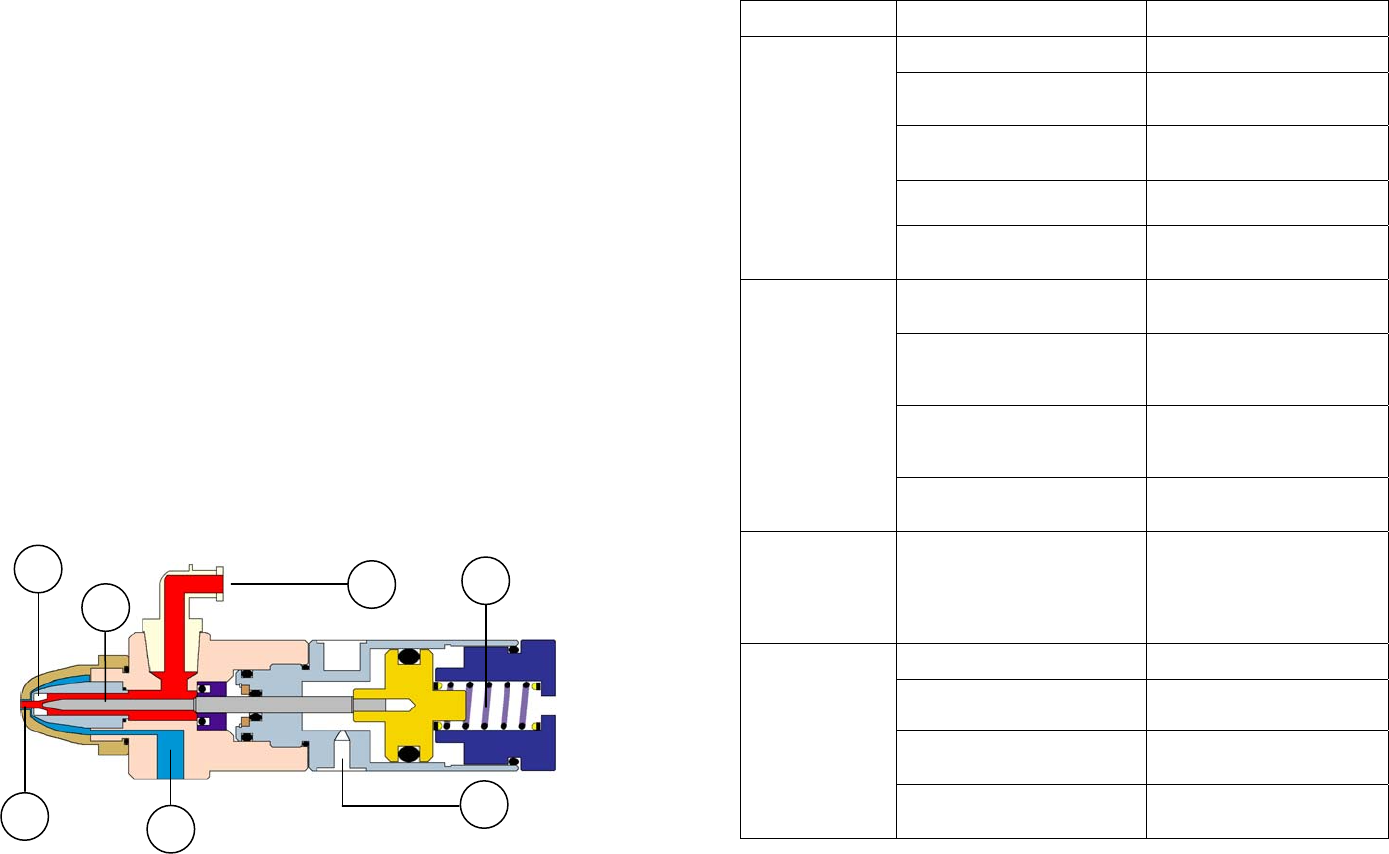
The TS5520 Series Spray Valve is a normally closed, adjustable opening, needle
and seat valve. Inlet air pressure through port (2) retracts the needle assembly (7)
from the seat (4) allowing fluid to flow from the valve fluid inlet (6) to the outlet
nozzle (5). Air pressure through port (3) passes around the dispense “orifice”
providing the atomized spray pattern. Relieving the input air pressure allows the
spring (1) to return the needle back to its position to close the material path.
Figure 2.0
6
4
7
5
1
2
3
13
11. TROUBLE SHOOTING
PROBLEM POSSIBLE CAUSE CORRECTION
No Fluid Flow
Fluid pressure too low Increase fluid pressure
Operating pressure too low
Increase air pressure to 70 psi
(4.8bar)
Valve is not actuating Check Valve controller
Fluid cured in valve chamber Clean valve thoroughly
The stroke adjustment closed
Open stroke adjustment
counterclockwise
Inconsistent
Fluid Flow
Fluid pressure fluctuating
Make sure fluid pressure is
constant
Valve operating pressure is too
low
Increase valve pressure to 70
psi (4.8bar)
Valve open time is not
consistent
Check to make sure the valve
controller is providing a
consistent output
Air trapped in fluid housing Purge valve
Fluid drools after
the valve closes,
eventually
stopping
Air trapped in fluid housing Purge valve
Fluid flows
through nozzle
but will not spray
Steady drip
Atomize pressure is too low Increase atomize pressure
Dirty needle and seat Perform thorough cleaning
Worn needle and seat
Replace worn or damaged
part
Fluid pressure exceeds 100 psi
(6.9bar)
Lower fluid pressure
12
10. STANDARD ACCESSORIES
10.1 OPTIONAL ACCESSORIES
10.2 FLUID FITTINGS AND TUBING
10.3 BRACKETS
PART NUMBER DESCRIPTION
5520F-000-001 Collar for Fan Cap
5520F-000-002 Fan Cap for “Elliptical” Spray Pattern
PART NUMBER DESCRIPTION
TS918-46 4-Way Fluid Manifold
5420-SIT Seal Insertion Tool
PART NUMBER DESCRIPTION
TSD1003-16 ⅛'' NPT to ¼'' O.D. Tube, 90° Elbow
TSD1002-17 ⅛'' NPT to ⅜'' O.D. Tube
TSD1002-18 ⅛'' NPT to ¼'' O.D. Tube
TSD1002-38 ¼'' NPT to ¼'' O.D. Tube
TSD1099-22 ⅜'' O.D. X ¼'' I.D. Tube, Black, Polyethylene
TSD1099-23 ⅜'' O.D. X ¼'' I.D. Tube, Clear, Polyethylene
TSD1099-24 ¼'' O.D. X ⅛'' I.D. Tube, Clear, Polyethylene
TSD1099-25 ¼'' O.D. X ⅛'' I.D. Tube, Black, Polyethylene
TSD1099-45 6mm O.D. X 4mm I.D, Clear, Polyethylene
TSD1099-46 6mm O.D. X 4mm I.D, Black, Polyethylene
TSD126-360BPK Luer Lock Tubing, 60'' (1524mm) , Black
PART NUMBER DESCRIPTION
918-033-000 Productions Master Stand (Base & Support)
918-000-012 Rod Clamp Assembly
1212-000-008 6'' (152.4mm) Threaded Mounting Rod
5
5. SETUP INSTRUCTIONS
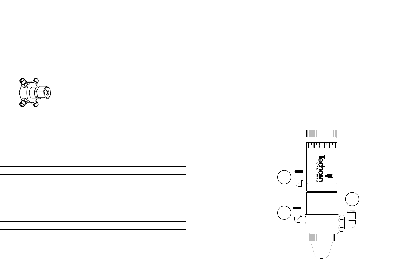
Refer to Figure 3.0
Note: This installation uses Luer lock adapters shipped with the valve. Any
approved material line with ⅛''
NPT connections will work.
1. If desired, mount the valve to the mounting
b
racket included.
2. Connect fluid feed line to fluid inlet port (2).
3. Install the valve actuating air hose to the valve air inlet (1).
4. Install the atomize air hose to the valve atomize air inlet (3).
5. Connect the valve actuating air hose (1) to Port A of the TS500R controller.
6. Connect the atomize air hose (3) to Port B of the TS500R controller.
7. Make sure all connections are tight.
8. Set fluid pressure. Do not exceed 100 psi (6.9bar).
9. Place container under the valve outlet and activate the valve until the fluid
flows steady.
Figure 3.0
1
3
2
6
6. TYPICAL SYSTEM SET-UP
SPRAY AREA COVERAGE BY ROUND NOZZLE:
Distance from
Nozzle
1
''
(25.40mm)
2''
(50.80mm)
3''
(76.20mm)
6''
(152.40mm)
Diameter of spray
pattern
0.250''
(6.35mm)
0.500''
(12.70mm)
0.750''
(19.05mm)
1.500''
(38.10mm)
SPRAY AREA COVERAGE BY FAN NOZZLE:
Distance from
Nozzle
1''
(25.40mm)
2''
(50.80mm)
3''
(76.20mm)
6''
(152.40mm)
Diameter of spray
pattern
1.000''
(25.40mm)
1.500''
(28.10mm)
2.000''
(50.80mm)
3.250''
(82.60mm)
Spray coverage is determined by:
• Flow adjustment - turn end cap counterclockwise to increase material flow rate.
• Length of actuation, set at controller (valve open time).
• Fluid reservoir pressure
• Fluid viscosity
Figure 4.0
11
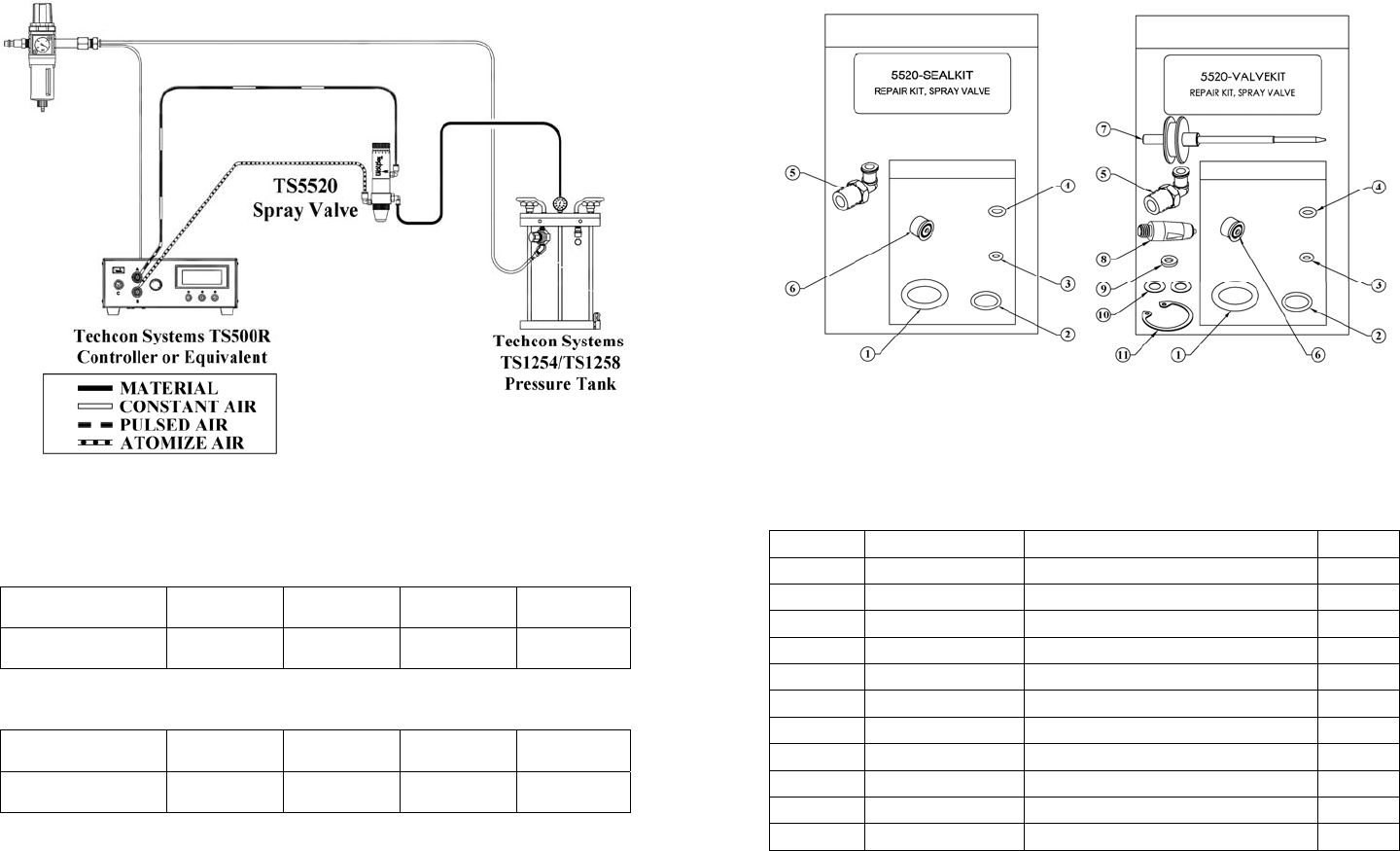
9. REPAIR KITS
ITEM PART NUMBER DESCRIPTION QTY
1 TSD1400-208A Piston O-Ring, Buna 1
2 TSD1400-013A O-Ring, Buna 1
3 TSD1400-006A O-Ring, Buna 1
4 TSD1400-008A O-Ring, Buna 1
5 TSD931-75 Luer Lock Adaptor, Elbow 1
6 TSD400-70 U-Cup Seal 1
7 5520-000-010 Needle/Piston Assembly 1
8 5520-000-020 Nozzle, Inc. Seat 1
9 TSD1109-45 Nylon Washer 1
10 TSD1109-43 Mylar Washer 2
11 TSD1120-15 Retaining Ring, Large 1