TS5520-user-guide.pdf - 第6页
6 6. TYPICAL SYSTEM SET-UP SPRAY AREA COVERAGE BY ROUND NOZZLE: Distance from Nozzle 1 '' (25.40mm) 2 '' (50.80mm) 3 '' (76.20mm) 6 '' (152.40mm) Diameter of spra y pattern 0.250 &…
12
10. STANDARD ACCESSORIES
10.1 OPTIONAL ACCESSORIES
10.2 FLUID FITTINGS AND TUBING
10.3 BRACKETS
PART NUMBER DESCRIPTION
5520F-000-001 Collar for Fan Cap
5520F-000-002 Fan Cap for “Elliptical” Spray Pattern
PART NUMBER DESCRIPTION
TS918-46 4-Way Fluid Manifold
5420-SIT Seal Insertion Tool
PART NUMBER DESCRIPTION
TSD1003-16 ⅛'' NPT to ¼'' O.D. Tube, 90° Elbow
TSD1002-17 ⅛'' NPT to ⅜'' O.D. Tube
TSD1002-18 ⅛'' NPT to ¼'' O.D. Tube
TSD1002-38 ¼'' NPT to ¼'' O.D. Tube
TSD1099-22 ⅜'' O.D. X ¼'' I.D. Tube, Black, Polyethylene
TSD1099-23 ⅜'' O.D. X ¼'' I.D. Tube, Clear, Polyethylene
TSD1099-24 ¼'' O.D. X ⅛'' I.D. Tube, Clear, Polyethylene
TSD1099-25 ¼'' O.D. X ⅛'' I.D. Tube, Black, Polyethylene
TSD1099-45 6mm O.D. X 4mm I.D, Clear, Polyethylene
TSD1099-46 6mm O.D. X 4mm I.D, Black, Polyethylene
TSD126-360BPK Luer Lock Tubing, 60'' (1524mm) , Black
PART NUMBER DESCRIPTION
918-033-000 Productions Master Stand (Base & Support)
918-000-012 Rod Clamp Assembly
1212-000-008 6'' (152.4mm) Threaded Mounting Rod
5
5. SETUP INSTRUCTIONS
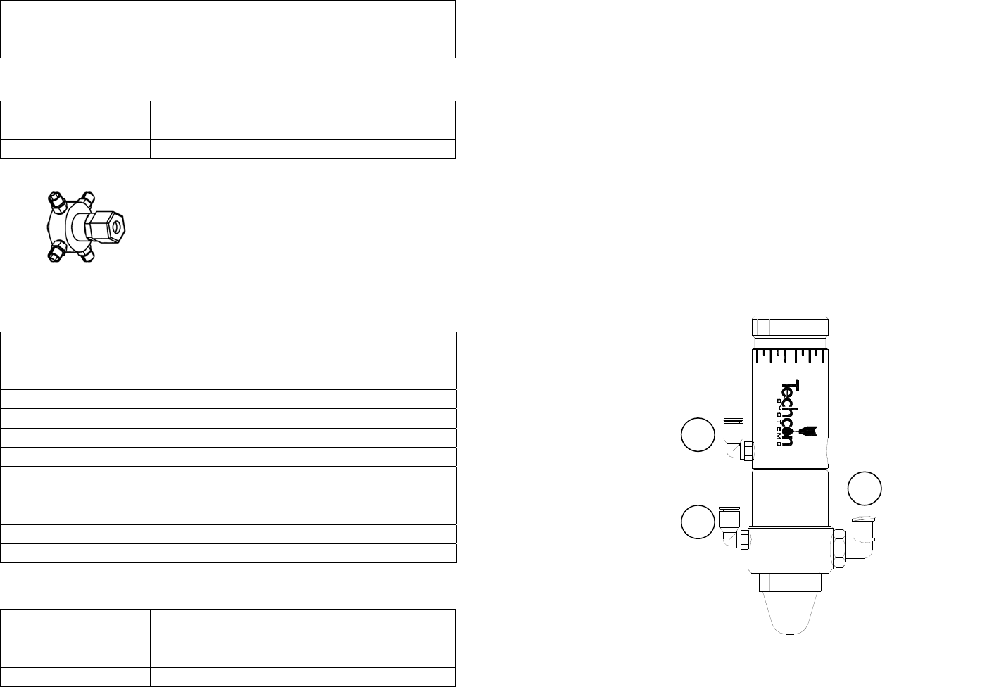
Refer to Figure 3.0
Note: This installation uses Luer lock adapters shipped with the valve. Any
approved material line with ⅛''
NPT connections will work.
1. If desired, mount the valve to the mounting
b
racket included.
2. Connect fluid feed line to fluid inlet port (2).
3. Install the valve actuating air hose to the valve air inlet (1).
4. Install the atomize air hose to the valve atomize air inlet (3).
5. Connect the valve actuating air hose (1) to Port A of the TS500R controller.
6. Connect the atomize air hose (3) to Port B of the TS500R controller.
7. Make sure all connections are tight.
8. Set fluid pressure. Do not exceed 100 psi (6.9bar).
9. Place container under the valve outlet and activate the valve until the fluid
flows steady.
Figure 3.0
1
3
2
6
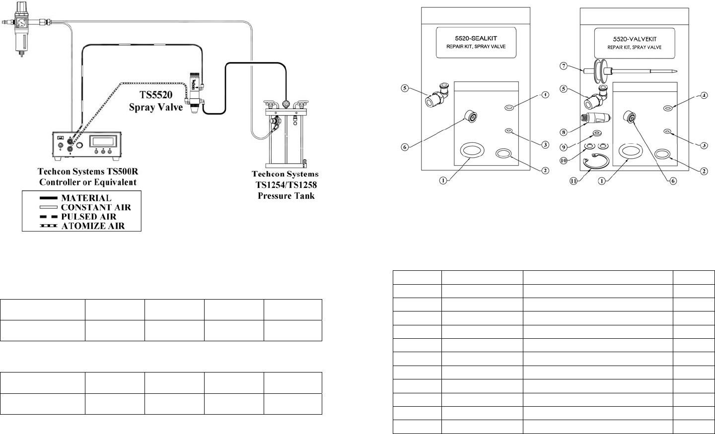
6. TYPICAL SYSTEM SET-UP
SPRAY AREA COVERAGE BY ROUND NOZZLE:
Distance from
Nozzle
1
''
(25.40mm)
2''
(50.80mm)
3''
(76.20mm)
6''
(152.40mm)
Diameter of spray
pattern
0.250''
(6.35mm)
0.500''
(12.70mm)
0.750''
(19.05mm)
1.500''
(38.10mm)
SPRAY AREA COVERAGE BY FAN NOZZLE:
Distance from
Nozzle
1''
(25.40mm)
2''
(50.80mm)
3''
(76.20mm)
6''
(152.40mm)
Diameter of spray
pattern
1.000''
(25.40mm)
1.500''
(28.10mm)
2.000''
(50.80mm)
3.250''
(82.60mm)
Spray coverage is determined by:
• Flow adjustment - turn end cap counterclockwise to increase material flow rate.
• Length of actuation, set at controller (valve open time).
• Fluid reservoir pressure
• Fluid viscosity
Figure 4.0
11
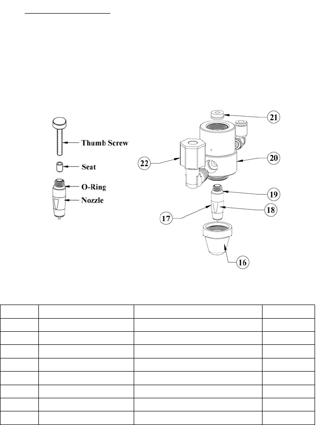
9. REPAIR KITS
ITEM PART NUMBER DESCRIPTION QTY
1 TSD1400-208A Piston O-Ring, Buna 1
2 TSD1400-013A O-Ring, Buna 1
3 TSD1400-006A O-Ring, Buna 1
4 TSD1400-008A O-Ring, Buna 1
5 TSD931-75 Luer Lock Adaptor, Elbow 1
6 TSD400-70 U-Cup Seal 1
7 5520-000-010 Needle/Piston Assembly 1
8 5520-000-020 Nozzle, Inc. Seat 1
9 TSD1109-45 Nylon Washer 1
10 TSD1109-43 Mylar Washer 2
11 TSD1120-15 Retaining Ring, Large 1
10
SPARE PARTS, CONT.
Valve Front Section
ITEM PART NUMBER DESCRIPTION QTY
16 5520-000-018 Spray Cone Cap 1
17 5520-000-020 Nozzle, Inc. Seat 1
18 T1000598 Nozzle Seat 1
19 TSD1400-008A Nozzle Adaptor O-Ring, Buna 1
20 5520-000-002 Body 1
21 TSD400-70 U-Cup Seal 1
22 TSD1003-16 Compression Fitting 1
Above TSD1113-28 Thumb Screw 1
Recommended lubricant:
All O-Rings & seals must be lubricated with Bimba HT-99, or equivalent, with
the exception of TSD400-70, which must remain dry.
Figure 6.0
7
• Distance between spray nozzle to spray surface
7. MAINTENANCE AND CLEANING:
Tool required: 5/8'' open-end wrench; Snap ring pliers, o-ring removal tool (P/N
TSD1597-7).
Normally, purging the valve with appropriate flush material or solvent after use is
sufficient for cleaning. However, some material may cause a buildup in the valve
chamber, in this case periodic and thorough cleaning will be required.
NOTE:
• Make sure the fluid pressure is released before valve is disassembled
• To replace seals, please order seal kit part number: 5520-SEALKIT
• To repair valve, please order valve kit part number: 5520-VALVEKIT
7.1 Thorough Cleaning
Refer to figure 5.0
1. Release fluid pressure.
2. Disconnect fluid line and remove fluid inlet fitting (28).
3. Disconnect valve air hoses.
4. Turn the stroke control knob (16) two turns counterclockwise from closed
position.
5. Hold the fluid housing (8) and rotate the air cylinder (2) counterclockwise.
When completely un-threaded, pull the two valve segments straight apart to
separate.
6. Inspect o-ring (6), replace o-ring if damaged found.
7. Remove cup seal (7), replace seal if damaged found.
8. Remove nozzle (10) and spray cone (9).
9. Clean the fluid housing (8), needle/piston assembly (5), nozzle (10) and
spray cone (9).
NOTE: Avoid using sharp probes for cleaning. Any nicks or scratches on the
seal or the surfaces of the needle/piston assembly may cause leakage.
10. Insert cup seal (7) into fluid housing (8) using 5420-SIT insertion tool.
Make sure the o-ring side is facing down.
11. Reinstall nozzle (10) and spray cone (9) to fluid housing (8).
12. Lubricate o-ring (6) with Bimba HT-99, or equivalent.
13. Thread the air cylinder/needle assembly into fluid housing.
14. Make sure not to cross thread.
7.2 Nozzle Seat Replacement (refer to figure 6.0)
1. Insert the thumb screw inside the nozzle (17) and rotate clockwise to attach
to the seat (18).
2. Secure the nozzle in a “soft jaw” vise and then pull the thumb screw, with
the seat attached, straight out.