吸嘴交换站ANCsensorAdjustStep.pdf - 第10页
Service Engineer Service Informati on No: SI120 5003E - 000 = ANC con trol board n ozzle sensor adjustmen t procedure 10 / 12 2.2 Clean the light path of the sensor 1. Remove the ANC nozzle storage part. Remove the nozz …
Service Engineer
Service Information
No: SI1205003E-000= ANC control board nozzle sensor adjustment procedure
9/12
2. Clean the parts of the ANC related to nozzle detection
If the nozzle storage part of the ANC gets dusty, the reaction of the sensor becomes unstable.
Make sure to clean the area regularly.
2.1 Clean the Acrylic board
1. Shut off the main air supply of the machine.
Turn the air pressure supply/shutoff switch to the “Shutoff” side in order to shut off the air supply
to the machine and release the residual pressure.
2. Close the ANC shutter by hand.
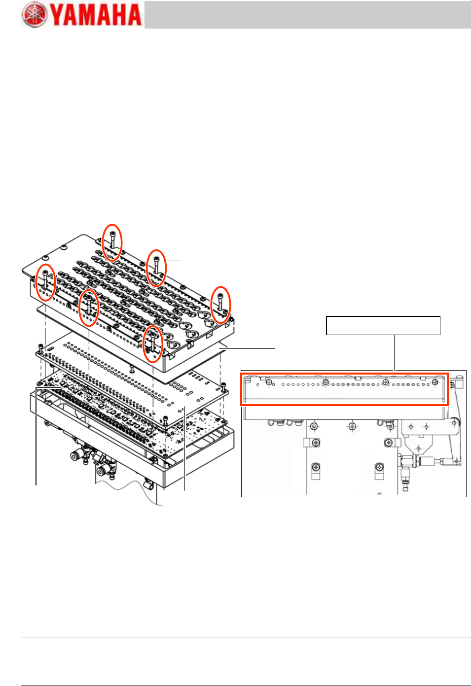
3. Remove the nozzle storage part from the ANC body.
Remove the six (6) fixing screws and remove the nozzle storage part from the ANC body.
Figure 13
4. Remove the dust on the surface of the acrylic board.
After removing the nozzle holder, if the acrylic board under the holder is dusty, clean it with soft
cloth.
5. Attach the nozzle storage part on the ANC body.
Clean the mounting surface of the nozzle storage part, and attach the nozzle storage part so that
the ANC shutter position matches the position of the cylinder for opening/closing the shutter.
The position is determined by the two (2) positioning pins, so the coordinate adjustment is not
required after attaching the nozzle storage part.
Caution:
If a chip or dust gets between the mounting surface and the nozzle storage part, the ANC coordinate
changes, and the nozzle change cannot be performed automatically. Make sure to clean the surface
beforehand.
Fixing screw for the
nozzle storage part
(Qty: 6)
ANC nozzle storage part
ANC control board Assy.
LED shield plate
Acrylic board
Service Engineer
Service Information
No: SI1205003E-000= ANC control board nozzle sensor adjustment procedure
10/12
2.2 Clean the light path of the sensor
1. Remove the ANC nozzle storage part.
Remove the nozzle storage part in the same manner as when cleaning the acrylic plate.
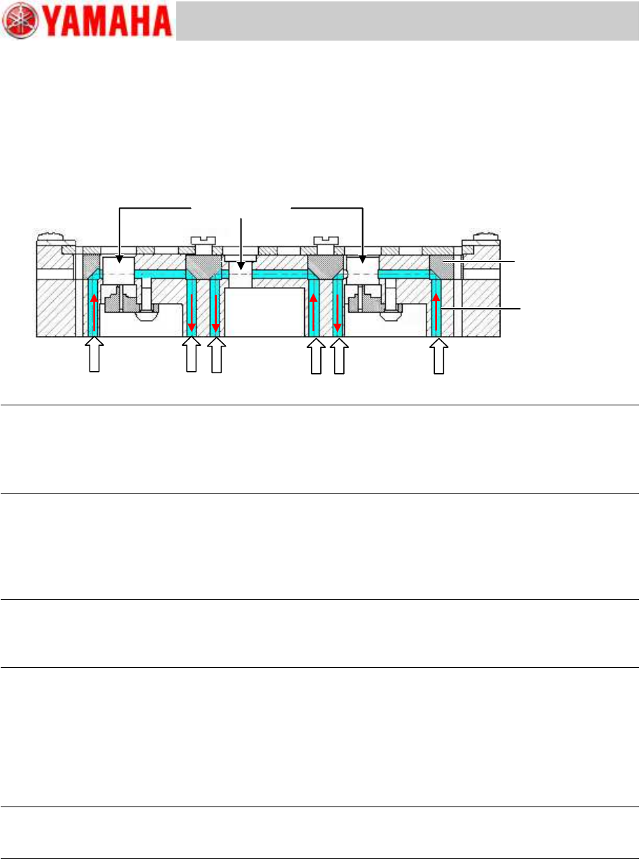
2. Blow air into the station hole and sensor light path around the nozzle in the ANC nozzle
storage part to remove the dust.
Figure 14
Note:
If the station holes and the sensor light paths are too dusty, remove all the nozzles from the station and
blow air.
Make sure to use the dry and clean air.
If you use the contaminated air, the reflecting mirror gets dusty which weakens the sensor light.
4. Attach the nozzle storage part to the ANC body.
Clean the mounting surface of the nozzle storage part, and attach the nozzle storage part so that
the ANC shutter position matches the position of the cylinder for opening/closing the shutter.
The position is determined by the two (2) positioning pins, so the coordinate adjustment is not
required after attaching the nozzle storage part.
Caution:
If a chip or dust gets between the mounting surface and the nozzle storage part, the ANC coordinate
changes, and the nozzle change cannot be performed automatically. Make sure to clean the surface
beforehand.
2.3 Adjust the sensor threshold
After cleaning the ANC nozzle storage part, adjust the sensor threshold.
Perform the adjustment by using the CalibSm “ANC Manual” utility.
The adjustment method is the same as the method for checking the nozzle detection condition.
See “1.2 Check the threshold of the sensor by the CalibSm”.
Note:
If the nozzles can be changed automatically, it is recommended to use the “All Nozzle Adjust” function
for the adjustment.
Station hole for
storing the nozzle
Reflecting mirror
Sensor light path
Service Engineer
Service Information
No: SI1205003E-000= ANC control board nozzle sensor adjustment procedure
11/12
3. Countermeasure for the LED light leak from the ANC control
board area
Some improvements have been made to stabilize the sensitivity of the ANC control board nozzle
sensors for the YS24X model.
Countermeasure for the LED light leak due to the deformation of the LED shield plate
<Symptom>
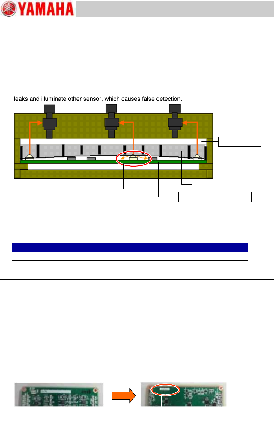
When the LED shield plate warps due to aging or moisture absorption, the emitter side LED light
leaks and illuminate other sensor, which causes false detection.
Figure 15
<Countermeasure>
The thickness of the acrylic board has been changed from 1.5mm to 2.0mm. Press the entire
surface of the LED shield with the plate.
If the thickness of the currently used acrylic board is 1.5mm, it is recommended to change it to the
2.0mm thick one.
Item
Part Name
Part No.
Qty
Note
Acrylic board
BOARD, CLEAR
KKT-M9610-001
1
Thickness: 2.0mm
Table 1
* The 2.0mm thick acrylic board is used for the machines shipped in and after September 2012.
Note:
When changing the acrylic board from the 1.5mm thick one to the 2.0mm thick one, make sure to
readjust the sensor threshold and check and adjust the ANC height coordinate.
Countermeasure for the LED light leak due to the inappropriate position of the sticker on
the ANC control board
<Symptom>
In the YS24X machines, there are cases that the LED light leaks depending on the position and
the condition of the serial number sticker on the board surface (LED mounting surface).
<Countermeasure>
The situation may be improved by changing the position of the serial number sticker from on the
upper surface (LED mounting surface) to the reverse side surface (IC mounting surface).
Figure 16
Acrylic board
LED Shield plate
ANC Control board Assy.
The LED light leaks through the gap
between the ANC control board and the
LED shield plate.
Stick the Serial No. sticker on the
reverse side of the board.