吸嘴交换站ANCsensorAdjustStep.pdf - 第9页
Service Engineer Service Informati on No: SI120 5003E - 000 = ANC con trol board n ozzle sensor adjustmen t procedure 9/ 12 2. Clean the p arts of the A NC related to nozzle detection If the nozz le storage part of the A…
Service Engineer
Service Information
No: SI1205003E-000= ANC control board nozzle sensor adjustment procedure
8/12
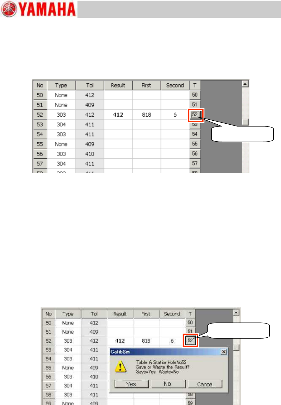
4. Perform teaching for the detection level when the nozzles is out of the station.
Take out the nozzle from the No.52 station and click the [52] button on the right side of the
window.
The sensitivity (Threshold) when the nozzle is taken out of the station is displayed in the “Second”
field.
Also the value intermediate between the results of the first and the second round of measurement
is displayed in the “Result” field.
Figure 11
5. Check the measured result.
Repeat the measurement several times and make sure that there is enough difference
between the results of the first and the second round of measurement, and the difference
does not vary much.
Before shipment of the machine, the difference between the two measured results is set to
be approx. 800. However, if the difference is 400 or less even after cleaning the parts
related to nozzle detection, it is recommended to replace the ANC control board Assy.
Compare the “Tol” value (The current threshold) and the “Result” value (The threshold after
the measurement).
When there is not much difference between the “Tol” value and the “Result” value, save
the data.
If the difference is significant, identify the cause of it and take appropriate measures, and
perform the adjustment again.
6. Save the measured result.
When you need to save the measured result as the new threshold, click the [52] button on the “T”
column (“Teach” button).
Figure 12
7. Perform the adjustment for other nozzles.
If other sensors need to be adjusted, repeat the procedures from step 3 through step 6.
If other nozzles can be changed automatically, use the “ANC Auto” utility for the adjustment.
Click the [52] button.
Click the [52] button.
Service Engineer
Service Information
No: SI1205003E-000= ANC control board nozzle sensor adjustment procedure
9/12
2. Clean the parts of the ANC related to nozzle detection
If the nozzle storage part of the ANC gets dusty, the reaction of the sensor becomes unstable.
Make sure to clean the area regularly.
2.1 Clean the Acrylic board
1. Shut off the main air supply of the machine.
Turn the air pressure supply/shutoff switch to the “Shutoff” side in order to shut off the air supply
to the machine and release the residual pressure.
2. Close the ANC shutter by hand.
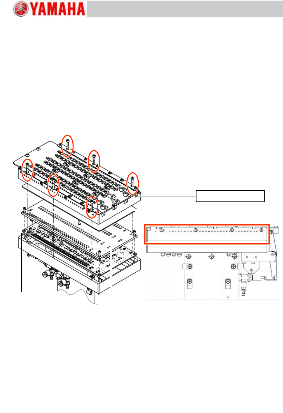
3. Remove the nozzle storage part from the ANC body.
Remove the six (6) fixing screws and remove the nozzle storage part from the ANC body.
Figure 13
4. Remove the dust on the surface of the acrylic board.
After removing the nozzle holder, if the acrylic board under the holder is dusty, clean it with soft
cloth.
5. Attach the nozzle storage part on the ANC body.
Clean the mounting surface of the nozzle storage part, and attach the nozzle storage part so that
the ANC shutter position matches the position of the cylinder for opening/closing the shutter.
The position is determined by the two (2) positioning pins, so the coordinate adjustment is not
required after attaching the nozzle storage part.
Caution:
If a chip or dust gets between the mounting surface and the nozzle storage part, the ANC coordinate
changes, and the nozzle change cannot be performed automatically. Make sure to clean the surface
beforehand.
Fixing screw for the
nozzle storage part
(Qty: 6)
ANC nozzle storage part
ANC control board Assy.
LED shield plate
Acrylic board
Service Engineer
Service Information
No: SI1205003E-000= ANC control board nozzle sensor adjustment procedure
10/12
2.2 Clean the light path of the sensor
1. Remove the ANC nozzle storage part.
Remove the nozzle storage part in the same manner as when cleaning the acrylic plate.
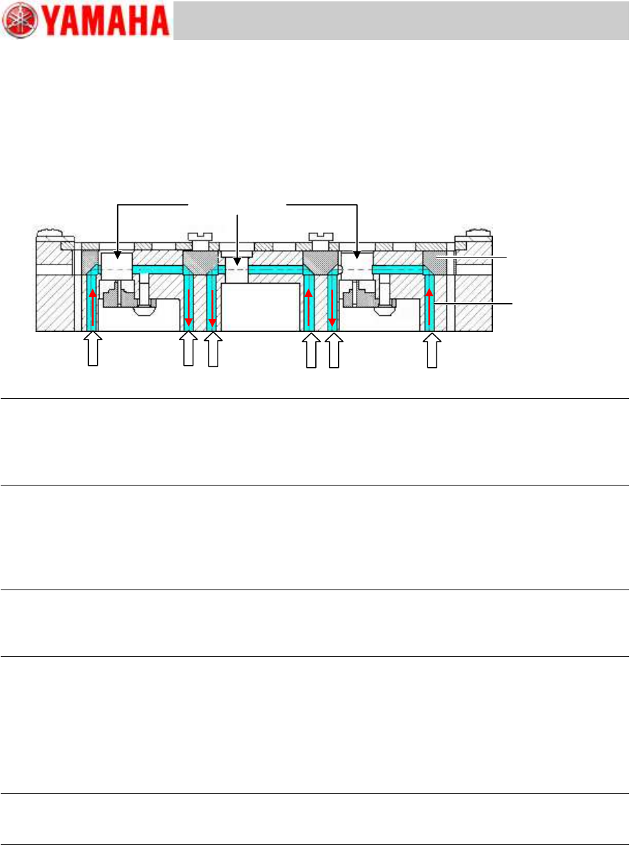
2. Blow air into the station hole and sensor light path around the nozzle in the ANC nozzle
storage part to remove the dust.
Figure 14
Note:
If the station holes and the sensor light paths are too dusty, remove all the nozzles from the station and
blow air.
Make sure to use the dry and clean air.
If you use the contaminated air, the reflecting mirror gets dusty which weakens the sensor light.
4. Attach the nozzle storage part to the ANC body.
Clean the mounting surface of the nozzle storage part, and attach the nozzle storage part so that
the ANC shutter position matches the position of the cylinder for opening/closing the shutter.
The position is determined by the two (2) positioning pins, so the coordinate adjustment is not
required after attaching the nozzle storage part.
Caution:
If a chip or dust gets between the mounting surface and the nozzle storage part, the ANC coordinate
changes, and the nozzle change cannot be performed automatically. Make sure to clean the surface
beforehand.
2.3 Adjust the sensor threshold
After cleaning the ANC nozzle storage part, adjust the sensor threshold.
Perform the adjustment by using the CalibSm “ANC Manual” utility.
The adjustment method is the same as the method for checking the nozzle detection condition.
See “1.2 Check the threshold of the sensor by the CalibSm”.
Note:
If the nozzles can be changed automatically, it is recommended to use the “All Nozzle Adjust” function
for the adjustment.
Station hole for
storing the nozzle
Reflecting mirror
Sensor light path