00198788-01_UM_SSI_DE_EN.pdf - 第52页
4 Operation 4.6 Tasks for Setup Center 52 User Manual / Bedienungsanleitung SIPLACE Single Slot Interface 05/2021 Scanning a barcode The SSI supports safe and reliable feeder kitting. The SSI offers the same safety mecha…
4 Operation
4.6 Tasks for Setup Center
User Manual / Bedienungsanleitung SIPLACE Single Slot Interface 05/2021 51
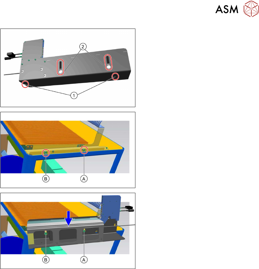
Assembly on a preparation table:
► When assembling on the preparation
table, use the hook-up slots (2)
on the
left side of the SSI steel frame.
► The right side of the preparation table
has slotted screws (A)
and (B) for
hooking up the SSI.
► Guide the hook-up slots on the steel
frame over the slotted screws (A)
and
(B)
and press the steel frame down-
wards.
4.6 Tasks for Setup Center
Configuring the SSI in Setup Center
In the main menu, select Extras -> Settings and then select the category Single Slot Interfaces
to configure the Single Slot Interfaces:
●
Add SSI
●
Removing the selected SSI
●
Editing the selected SSI
●
List of SSIs present
●
Updating information about a connected SSI
For details see the user manual "ASM Setup Center 9.8", section "Single Slot Configuring Setup
Center".
4 Operation
4.6 Tasks for Setup Center
52 User Manual / Bedienungsanleitung SIPLACE Single Slot Interface 05/2021
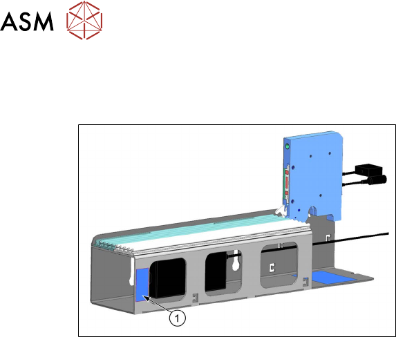
Scanning a barcode
The SSI supports safe and reliable feeder kitting. The SSI offers the same safety mechanisms as a
docking station with regard to the tape and foil status.
The SSI barcode (1) is located on the side of
the SSI frame.
For details see the user manual "ASM Setup Center 9.8", section "Offline feeder kitting with Single
Slot Interface".
5 CAN ID mode and presettings
5.1 CAN ID mode
User Manual / Bedienungsanleitung SIPLACE Single Slot Interface 05/2021 53
5 CAN ID mode and presettings
5.1 CAN ID mode
The SSI can be seen as a docking station with 1 track. Using a CAN bus cable, up to 4 SSIs can
be connected to the CIN box via a CAN bus. A different CAN ID must be set for each individual SSI
within the CAN bus so that the devices can be detected clearly.
5.2 Setting the CAN ID
The SSI CAN ID is set on the board using the DIP switch. The preset CAN ID is Hex 400.
WARNING
Unplug the mains connector from the power supply before opening the SSI.
When working with settings on the board, disconnect the SSI to protect the sensitive elec-
tronics assemblies.
NOTICE
Modified settings on the board will only be imported when the SSI is rebooted.
Settings defined on the board will only be imported when the SSI is rebooted. Booting will
occur as soon as the SSI is connected to the power supply.
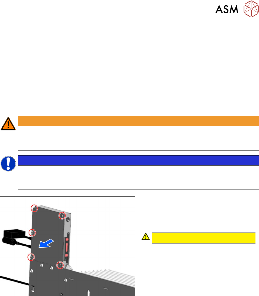
To set the CAN ID, proceed as follows:
► Remove the five the M3x6 hexagon
socket-head screws (see red outline):
► Remove the cover.
CAUTION!
ESD-sensitive electronics.
Observe the ESD regulations.
Use an ESD-safe workplace and ESD-
safe tools.
.