00198788-01_UM_SSI_DE_EN.pdf - 第56页
5 CAN ID mode and presettings 5.3 Setting the baud rate 56 User Manual / Bedienungsanleitung SIPLACE Single Slot Interface 05/2021 ► Close the panel. ► Tighten the previously removed five hexagon socket-head screws. NO…
5 CAN ID mode and presettings
5.3 Setting the baud rate
User Manual / Bedienungsanleitung SIPLACE Single Slot Interface 05/2021 55
5.3 Setting the baud rate
A jumper on the board can be used to define the baud rate used to transmit the SSI signals. The
preset rate is 1MBd for communication as a setup area (like FCU).
WARNING
Unplug the mains connector from the power supply before opening the SSI.
When working with settings on the board, disconnect the SSI to protect the sensitive elec-
tronics assemblies.
NOTICE
Modified settings on the board will only be imported when the SSI is rebooted.
Settings defined on the board will only be imported when the SSI is rebooted. Booting will
occur as soon as the SSI is connected to the power supply.
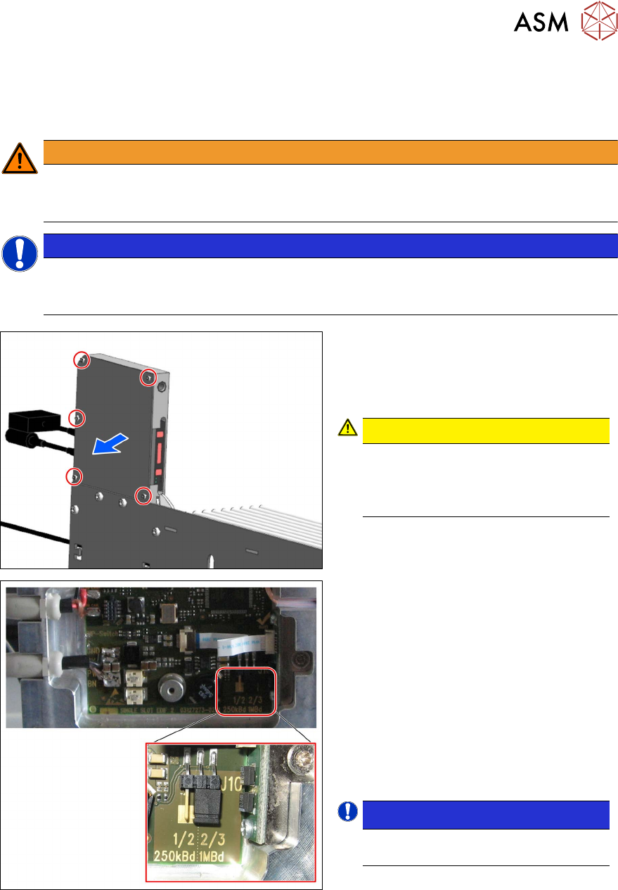
To set the baud rate, proceed as follows:
► Remove the five the M3x6 hexagon
socket-head screws (see red outline):
► Remove the cover.
CAUTION!
ESD-sensitive electronics.
Observe the ESD regulations.
Use an ESD-safe workplace and ESD-
safe tools.
.
► Set the required baud rate by selecting
the connector position.
Possible baud rate:
1. 250 kBd: connector at position 1/2
for communication with Caccia (ASM
in-house)
2. 1 MBd: connector at position 2/3
for communication as setup area (as
FCU)
In its delivery state, the connector is connec-
ted to position 2/3 and therefore preset to 1
MBd.
NOTICE!
If the connector is missing, 1MBd
is automatically selected.
.
5 CAN ID mode and presettings
5.3 Setting the baud rate
56 User Manual / Bedienungsanleitung SIPLACE Single Slot Interface 05/2021
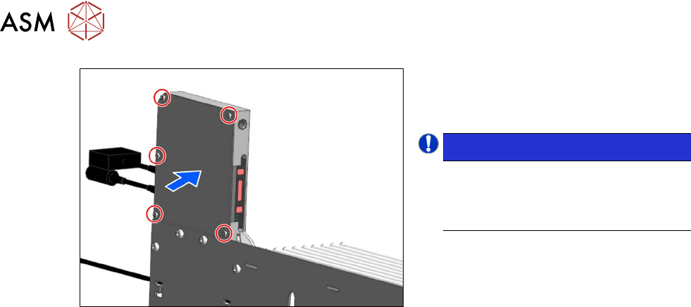
► Close the panel.
► Tighten the previously removed five
hexagon socket-head screws.
NOTICE!
The changed settings will only be
imported when the SSI is rebooted
i.e. when the SSI is reconnected to
the power supply.
.
6 Overviews
6.1 Block diagram of power pack and EDIF
User Manual / Bedienungsanleitung SIPLACE Single Slot Interface 05/2021 57
6 Overviews
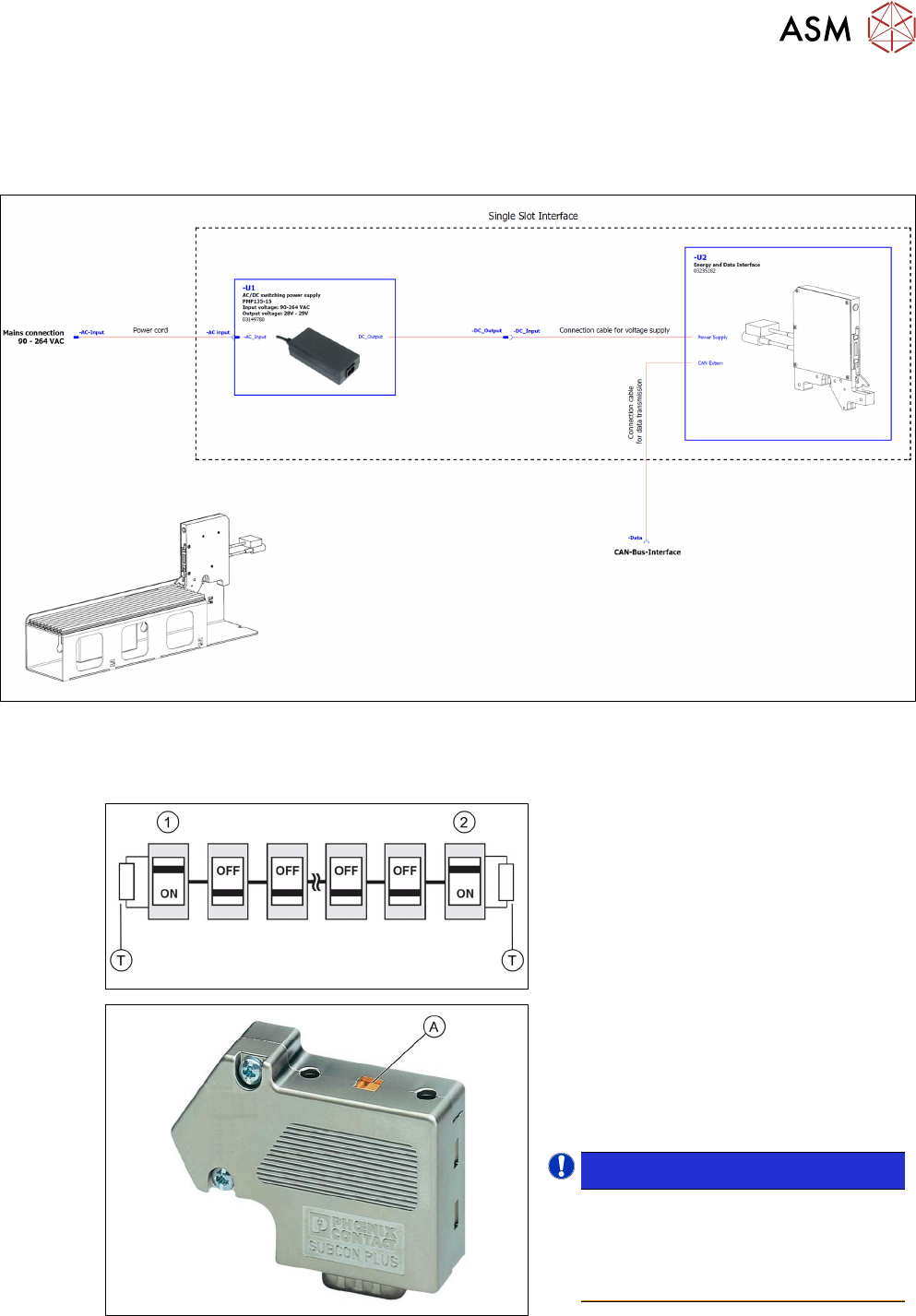
6.1 Block diagram of power pack and EDIF
Fig.4: Block diagram of power pack and EDIF
6.2 CAN bus cable, docking station, terminating resistor
The terminating resistors (T)are activated at
the beginning (1)
and end (2) of the bus sys-
tem. At the same time, the cable connection
terminals (2C+/2C-) for the continuing bus
cable are switched off.
► Push the sliding switch (A) on the SUB-
D connector at the beginning of the bus
system to ON.
► Push the sliding switch (A) on the SUB-
D connector at the end of the bus sys-
tem to ON.
NOTICE!
The terminating resistors at all
other nodes in the bus system must
be deactivated! The sliding switch
for the relevant SUB-D connector
must be set to OFF.
.