ECM-B3M-C20807SS1伺服电机-资料.pdf - 第52页
49 Dimensions of Motors with Frame Siz e of 80 mm or Below Model C 2 040F 3 4 5 C 2 0401 3 4 5 C 2 3 4 5 C 2 0604 3 4 5 C 2 0804 3 4 5 C 2 0807 3 4 5 LC 40 40 60 60 80 80 …
48
2
2
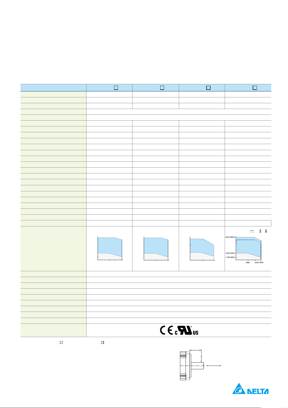
High Inertia Series Servo Motor
2
0602
*1
2
0604
*1
2
*1
2
*1
0.2 0.4 0.4
*2
0.64 1.27 1.27
2.24 4.44
6000
2.6 4.61
16.4
kg.m
2
0.441 0.479 0.49
16.4 17.2 17. 9
1.19
4.2 2.2
2.14 2.40
*4
7.2 7.2
20 20 20 20
60 60
74 74 147 147
10
0.32 (50%)
0.64 (100%)
2.24 (350%)
3000
6000
1.9 (306%)
4300
Torque (N - m)
Speed (rpm)
Intermittent Duty Zone
Continuous Duty Zone
0.65 (50%)
1.27 (100%)
4.45 (350%)
3000
6000
4200
3.9 (307%)
Torque (N - m)
Speed (rpm)
Intermittent Duty Zone
Continuous Duty Zone
0
4
1
3
4300
6000
3000
.635 (50%)
.44 (350%)
.27 (100%)
.28 (258%)
Torque (N - m)
Speed (rpm)
Intermittent Duty Zone
Continuous Duty Zone
Torque (N - m)
Speed (rpm)
Intermittent Duty Zone
Continuous Duty Zone
Insulation Class
Insulation Strength
Operating Temperature
Storage Temperature
20
1
represents the motor inertia and
2
Radial load
Thrust / axial load
LR-5
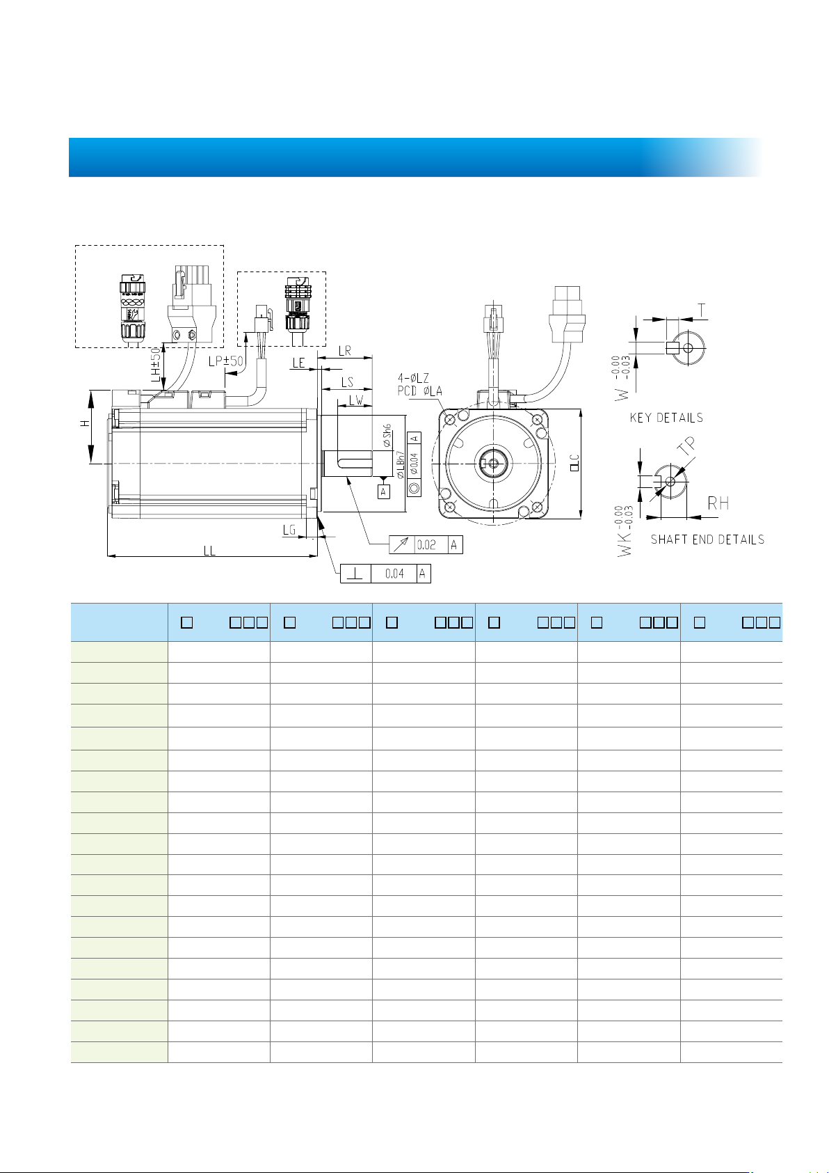
49
Dimensions of Motors with Frame Size of 80 mm or Below
Model C
2
040F
3
4
5
C
2
0401
3
4
5
C
2
3
4
5
C
2
0604
3
4
5
C
2
0804
3
4
5
C
2
0807
3
4
5
LC 40 40 60 60 80 80
LZ
LA 46 46 70 70 90 90
S
+0
-0.009
)
+0
0.009
)
+0
-0.011
)
+0
-0.011
)
+0
-0.011
)
+0
-0.013
)
LB
+0
-0.021
)
+0
-0.021
)
+0
-0.025
)
+0
-0.025
)
+0
-0.030
)
+0
-0.030
)
84 106
LH
LP
H
LS 27 27 27
LR 25 25 40
LE
LG 5 5 8 8
LW 16 16 20 20 20 25
RH 11 11 11
5 5 5 6
W 5 5 5 6
T 5 5 5 6
TP
50
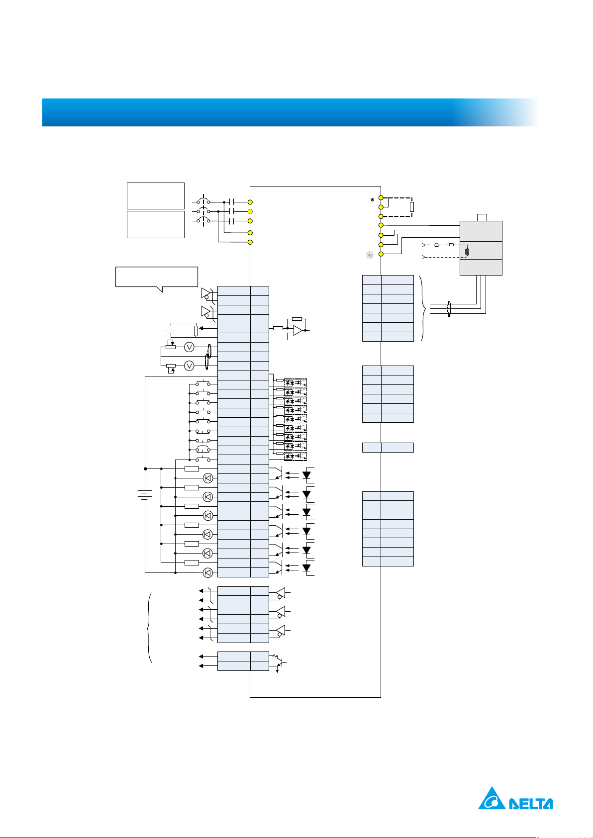
Control Mode Wiring
SON
CCLR
TCM0
TCM
1
ARST
NL
PL
EMGS
1.5 kΩ
SRDY
ZSPD
TPOS
HOME
ALRM
24V
A phase
differential signal
B phase
differential signal
Z phase
differential signal
Z phase open-
collector signal
Encoder
pulse
output
10 kΩ
±10V
Differential line driver for
position pulse input
*1
1.5 kΩ
1.5 kΩ
1.5 kΩ
1.5 kΩ
GND
OCZ
40
44
19
14
11
9
10
34
8
33
32
T-REF
GND
MON1
GND
MON2
COM+
DI1-
DI2-
DI3-
DI4-
DI5-
DI6-
DI7-
DI8-
DO1+
DO1-
DO2+
DO2-
DO3+
DO3-
DO4+
DO4-
DO5+
DO6-
OA
/OA
OB
/OB
OZ
/OZ
18
19
17
30
31
7
6
5
4
3
2
1
26
28
21
15
22
13
24
25
23
T+
T-
Shield
5
6
Case
-
-
-
RS485+
RS485-
GND_ISO
6,8
5
4
3,7
2
1
CN2
CN3
CN4
CN1
P
D
C
U
V
W
Max. output current: 50 mA
voltage: 30V
R
S
T
L
1C
L
2C
MC
MCCB
Servo drive
B3-L / B3A-L series
1.2 kΩ
Regenerative
resistor
Red
White
Black
Yellow /
Green
Brake
Power
supply
Encoder
BRKR
EMGS
24V
*2
*
4
4.7 kΩ
12DI9-
DO5-
DO6+
27
16
+5V
GND
1
2
Mini USB
*3
SG
Shielded
twisted-pair
cable
12 kΩ
10 kΩ
10 kΩ
1.5 kΩ
Do n ot con nect
this pin
Do n ot con nect
this pin
3
4
SIGN
SIGN-
37
SIGN
SIGN+
39
PULSE- 41
PULSE+
43
4.7 kΩ
4.7 kΩ
4.7 kΩ
4.7 kΩ
4.7 kΩ
4.7 kΩ
4.7 kΩ
4.7 kΩ
AC 200 / 230V
Three-phase
*5
50 / 60 Hz
AC 380 / 440V
Three-phase
50 / 60 Hz
-
1
-
2
SF1+
3
SF1-
4
SF2+
5
SF2-
6
EDM+
7
EDM-
8
CN10
STO (only supported by B3A)
Shielded
twisted-pair
cable
The supply voltage is 2.8 – 3.6V.
Do not input 24V power.