RC200-Manual-1.pdf - 第4页
Dual S ole noid Tool K it PVA offers standard tool kits for all dispensing valves. The tool kit for the RC200 is part number B12-2866 , which includes all necessary tools and lubricatin g greas e to perform maintenance o…
Safety
Due to material contents being under pressure eye protection is required for
operators. Refer to MSDS sheets on material being dispensed for other precautions.
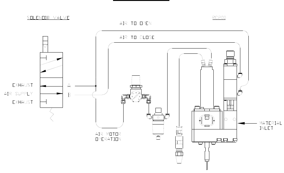
Setup
The RC200 requires a 2-position, 4-way air solenoid valve to actuate the air
section to open and close the valve. A precision air regulator and oil lubricator will be
connected in line to simultaneously activate the air motor. The valve should be operated
with clean, dry air between 60-100psi. Two #10-32 threaded air ports are located on the
air section of the FC100-Module and two 1/8”mnpt ports located on the air motor. The
port located furthest from the midsection of the FC100-Module is air to close the valve.
The port located closest to the mid-section of the FC100-Module is air to open the valve.
The air motor is marked with a forward and reverse control port to determine the direction
of rotation. Quick connect air fittings are typically supplied with the FC100 Module to fit
5/32” tubing while quick connect air fittings are supplied with the air motor to fit ¼”od
tubing. Note that the valve should be normally in the closed position.
Fluid is supplied to the RC200 valve through the 1/8”npt port located on the
stainless steel fluid section of the valve.
The muffler of the air motor should be run a distance several feet from the valve
to reduce noise in the work area. A small amount of air motor lubricant will be exhausted
from the muffler.
Single Solenoid
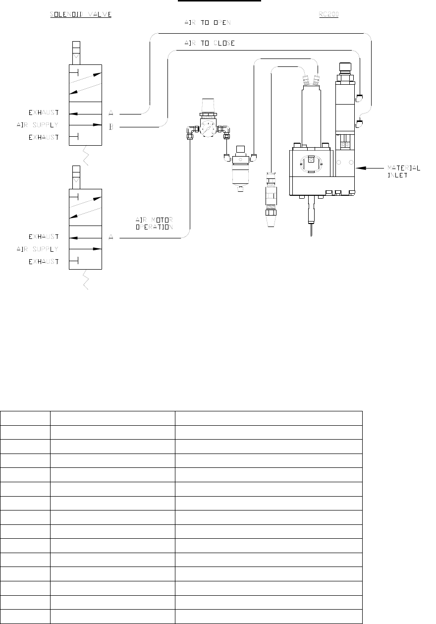
Dual Solenoid
Tool Kit
PVA offers standard tool kits for all dispensing valves. The tool kit for the RC200
is part number B12-2866, which includes all necessary tools and lubricating grease to
perform maintenance on this dispense valve:
B12-2866 Includes:
Qty
Part Number
Description
1
0266244
8” Adjustable Wrench
1
26569
9/64” Allen Key
2
26563
3/32” Allen Key
1
26561
5/64” Allen Key
1
26559
1/16” Allen Key
2
0216173
M7 Wrench
1
5516A18
Tweezers
1
B62-0752
2.5cc Mineral Oil Lubrication Kit
1
B62-2048
2.5cc Silicone Lubricant
1
27001
Lubricant for Air Motor
1
9570K71
Hook and Pick Set
1
0266255
Pliers
2
53085A61
Soft Plastic Covers for Pliers
1
MM115
Removable Thread Locker

Operation
Refer to assembly drawings 112-2998 & 112-3616 for part reference numbers.
1) Plumb up the valve as outlined above in the Setup procedures.
2) Fill the air motor lubricator with oil (27001) provided with the valve.
3) Regulate the air pressure operating the FC100-Module portion of the valve
between 60-100psi.
4) Making sure that the coating nozzle is inserted into a protective cylinder, cycle the
valve several times. When the valve is cycling, the needle (1A) can be seen going
up and down in the center and the air motor will be spinning the rotary shaft (3).
If the air motor is not spinning, increase the air pressure until it begins to turn.
The air motor typically requires a minimum of 20 psi in order to start spinning.
5) Again, cycle the valve several times to ensure the valve is opening and the air
motor is spinning with each cycle.
Note: If the valve is not cycling properly, refer to the Troubleshooting section.
6) When the fluid delivery system is connected to the valve, pressurize the material
to be dispensed. The suggested starting pressure range is less than 5 psi.
7) Again, insert the nozzle of the valve into a protective cylinder in order to contain
the material that will be sprayed.
8) Once again, cycle the valve open to purge. Fluid should begin to spray in a 360’
degree pattern from the output of the coating nozzle.
9) Check the fluid connection and packing nut (16A) for leaks. If the valve is
leaking, refer to the Troubleshooting section.
10) Adjust the fluid pressure in order to control the rate of fluid flow to the spray
nozzle.
11) The stroke adjustment (12A) can also be used to fine tune the fluid flow. Turning
the adjustment clockwise will decrease the material flow rate and counter-
clockwise will increase the material flow rate. If the stroke adjustment bolt is
turned all the way down it will stop the flow of fluid entirely.
12) Once the stroke adjustment setting is determined, use the adjustable wrench to
tighten the lock nut (11A) up against the upper air body (10A).
Note: Refer to Troubleshooting section for any problems.
Periodic Maintenance
1) Visually check the see through chamber of the air motor lubricator daily and refill
when it runs empty.
2) Lubricate the packing (15A) on the FC100-Module every 200 hrs by placing a
few drops of mineral oil or other light oil inside the packing nut.
*Note: PVA offers a 2.5cc mineral oil lubrication kit; Part#: B62-0752
3) The packing nut (16A) will require occasional tightening, as wear occurs in order
to prevent leaks through the packing.