RC200-Manual-1.pdf - 第7页
9) From the stainless ste el fluid sec tion of the v alve , unthre a d and remove the packing nut (16A), and the packing (15A ). 10) Usi ng t he pliers pull the seat (13A) out of the fluid section (14A ) and remo ve th e…
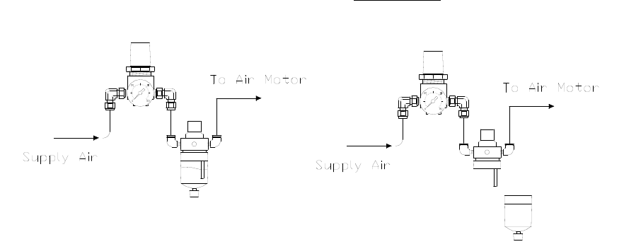
Air Motor Lubricator
The air motor must stay lubricated with a small amount of light oil in order to
maintain a long usable life. An air motor lubricator and oil are supplied with the RC200
valve. The oil level can be seen through the clear chamber on the bottom section of the
lubricator. When the oil runs out it will be necessary to refill the chamber. To do this
simply unthread and remove the clear chamber to separate the sections. These parts
should separate easily. Once removed, fill the clear chamber about half way with air
motor oil and thread the chamber back onto the housing, hand tight.
*Note: PVA offers additional tubes of air motor oil; Part#: 27001
*Note: During this operation, be sure air pressure is removed from system.
Routine Cleaning and Disassembly
Cleaning and rebuilding the valve will be required from time to time. A spare
parts kit, part # RC2-SP is available with all the normal wear parts included.
1) Begin disassembly by removing air and fluid pressure from the valve.
2) Remove all pneumatic tubing and fluid delivery fittings, hoses, etc. from the
valve.
3) To remove the coating nozzle (2), place the M7 wrench on the flat of the rotary
shaft (3) and use the pliers to grab the coating nozzle, turning counter-clockwise
to remove.
4) Using the 3/32” Allen Key, unthread and remove the four machine screws (9) that
connect the FC100-Module to the fluid section of the RC200.
5) On the FC100-Module use the 3/32” Allen key to loosen the packing nut (16A).
6) Using the same 3/32” Allen key, evenly remove the two machine screws (3A) that
are located on the same corners as the standoffs (6A). Note during removal that
there is a spring (5A) forcing the air section away from the fluid section.
7) Pull the air section (red anodized portion) away from the fluid section (stainless
steel portion).
8) Clean off the tip of the stainless steel needle (1A).
9) From the stainless steel fluid section of the valve, unthread and remove the
packing nut (16A), and the packing (15A).
10) Using the pliers pull the seat (13A) out of the fluid section (14A) and remove the
006 Kalrez o-ring (18A) from the seat. Note: If stuck, the seat can be pushed
through from the opposite side of the fluid section.
11) Clean all of the wetted parts thoroughly with an appropriate solvent.
12) On the air section, use a standard 3/32” Allen Key to evenly remove the final two
machine screws (2A) that thread into the end cap (7A). Note: During removal that
the spring (5A) will force the air section apart.
13) Separate the upper air body (10A) from the lower air body (8A) to remove the
spring (5A) then slide the end cap (A) off of the needle (1A).
14) Holding the lower air body (8A) in one hand, grab the needle (1A) and push the
needle and piston (9A) assembly out of the lower air body.
15) Remove the 004 Buna o-ring (17A) from the lower air body (8A).
16) Hold the piston (9A) with an adjustable wrench then use a 5/64” Allen key to
unthread and remove the set screw (4A) to remove the needle (1A) then remove
the 014 Buna o-ring (20A) from the piston (9A).
17) Remove the 014 Buna o-ring (20A) from the upper air body (10A) and the 008
Buna o-ring from the stroke adjust bolt (12A).
18) Unthread the stroke adjust bolt (12A) from the upper air body (10A) and remove
the 008 Buna o-ring (12A).
19) On the fluid body (4) of the RC200 remove the 010 Kalrez o-ring (12) that sealed
against the FC100-Module.
20) Using the 3/32” Allen Key, remove the plug (11) from the fluid body (4).
21) Using the 1/16” Allen Key, loosen the set screw on the rotary shaft (3).
22) To remove the air motor (7) use the 9/64” Allen key to unthread and remove the
two machine screws (10) then slide the air motor away from the motor mount (5).
23) The rotary shaft (3) can now be pushed through the valve and removed through
the motor mount (5).
24) Using the 3/32” Allen Key, remove the two machine screws (9) that secure the
motor mount (5) to the fluid body (4) and separate the two sections to remove the
010 Kalrez o-ring (12).
25) Using the same 3/32” Allen Key, remove the two machine screws (8) that secure
the seal plate (6) to the fluid body (4) and separate the two sections to remove the
final 010 Kalrez O-Ring (12).
• Replace components with spares provided in the spare parts kit.
Assembly Instructions
General
• All o-rings must be lubricated with a small amount of silicone grease.
• A small amount of removable thread locker should be applied to the set screw (4A)
and the male thread of the standoffs (6).
• Assemble the air section of the FC100-Module and fluid section separately prior to
connecting the two assemblies.
Air Section
1) Assemble the stroke adjust (12A) and lock nut (11A) with the hex head toward
the knurled end of the bolt.
2) Mount one 008 Buna o-ring (19A) on the inside groove of the stroke adjust (12A).
3) Thread the stroke adjustment assembly into the upper air body (10A).
4) Mount one 014 Buna o-ring (20A) on the end of the upper air body (10A) and the
other 008 Buna o-ring (19A) on the end groove of the stroke adjust (12A). Back
out the stroke adjust by turning it counter clockwise to the end of its travel.
5) Drop the needle (1A) into the piston (9A) and assemble with the set screw (4A)
using an adjustable wrench and 5/64” Allen key to tighten.
6) Mount the 014 Buna o-ring (20A) onto the piston (9A).
7) Apply a small amount of silicone grease to the inside of the lower air body (8A)
then drop in the piston and needle assembly.
8) Mount the 004 Buna o-ring (17A) on the end of the needle and slide it down into
the groove in the end of the lower air body (8A).
9) Slide the end cap (7A) onto the needle up to the lower air body (8A), place the
spring (5A) on top of the piston (9A), and assemble the two air bodies using two
machine screws (2A) tightening with a 3/32” Allen key.
*Note: Be sure the air holes are lined up on the same face and will align with the
fluid inlet on the fluid section (14A).