e2e_d115-e1_9_5_csm1012586.pdf - 第10页
E2E 10 Safety Precautions Refer to Warranty and Limitations of Liability . This product is no t designed or rated for ensuring safety of persons eith er directly or indirectly. Do not use it for such p urposes. • Do not …
E2E
9
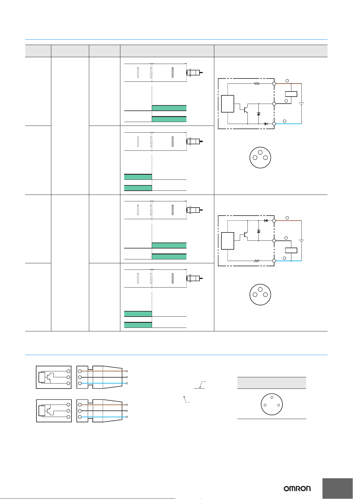
I/O Circuit Diagrams
Connection to I/O Connector (Connector Models, Pre-wired Connector Models)
Operation
mode
Output
specifications
Model Timing chart Output circuit
NO
NPN open-
collector
output
E2E-@@@@
-@@-C1
NC
E2E-@@@@
-@@-C2
NO
PNP open-
collector
output
E2E-@@@@
-@@-B1
NC
E2E-@@@@
-@@-B2
Sensing
object
Rated
sensing
distance
(%)
100 0
Sensing area
Non-sensing area
Proximity
Sensor
ON
OFF
ON
OFF
Operation
indicator
(yellow)
Control
output
Load
Brown
1
Black
Blue
Proximity
Sensor
main
circuit
10 to 30 VDC
31
4
Connector pin arrangement
M8
4
3
(%)
100 0
ON
OFF
ON
OFF
Proximity
Sensor
Sensing area
Non-sensing area
Sensing
object
Rated
sensing
distance
Operation
indicator
(yellow)
Control
output
Sensing
object
Rated
sensing
distance
(%)
100 0
Sensing area
Non-sensing area
Proximity
Sensor
ON
OFF
ON
OFF
Operation
indicator
(yellow)
Control
output
Load
10 to 30 VDC
Connector pin arrangement
M8
Proximity
Sensor
main
circuit
Brown
1
Black
4
Blue
3
31
4
(%)
100 0
ON
OFF
ON
OFF
Proximity
Sensor
Sensing area
Non-sensing area
Sensing
object
Rated
sensing
distance
Operation
indicator
(yellow)
Control
output
1
4
3
1
4
3
NPN
XS3F-M32@-3@@-R
1
4
3
1
4
3
PNP
02: 2 m
05: 5 m
1: Straight
2: Right-angle
Brown
Black
Blue
Brown
Black
Blue
Sensor I/O Connector
I/O connector cable,
connector arrangement diagram
31
4
E2E
10
Safety Precautions
Refer to Warranty and Limitations of Liability.
This product is not designed or rated for ensuring
safety of persons either directly or indirectly.
Do not use it for such purposes.
• Do not short the load. Explosion or burning may
result.
• Do not supply power to the Sensor with no load,
otherwise Sensor may be damaged.
Do not use this product under ambient conditions that exceed the
ratings.
● Design
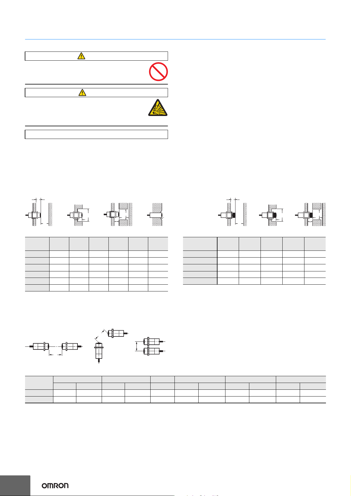
Influence of Surrounding Metal
When mounting the Sensor within a metal panel, ensure that the
clearances given in the following table are maintained. Failure to
maintain these distances may cause deterioration in the performance
of the Sensor.
〈Shielded Models〉
(Unit: mm)
〈Unshielded Models〉
(Unit: mm)
If mounted in a surrounding non-magnetic metal such as aluminum or copper, the sensing distance may shorten by about 40 to 50%.
If used in a recessed installation, take into consideration the effects of the material on the sensing distance.
Mutual Interference
When installing Sensors face-to-face or side-by-side, ensure that the minimum distances given in the following table are maintained.
Mutual Interference (Unit: mm)
* Values when the connector size is not taken into consideration.
WARNING
CAUTION
Precautions for Correct Use
Size
3 dia. 4 dia. 5.4 dia. 6.5 dia. M4 M5
Item
L 000000
m 353635
d 345.46.545
D 000000
n 810812810
c 000200
l
m
n
m
D
C
d dia.
L
Size
3 dia. 4 dia. 6.5 dia. M4 M5
Item
L 661266
m 69869
d 91224912
D 661266
n 16 20 24 16 20
l
m
n
m
D
d dia.
L
A
A
B
Size 3 dia. 4 dia. 5.4 dia. 6.5 dia. M4 M5
Item Shielded Unshielded Shielded Unshielded Shielded Shielded Unshielded Shielded Unshielded Shielded Unshielded
A 20 80 20 80 20 20 80 20 80 20 80
B * 15 60 15 60 15 15 60 15 60 15 60
E2E
11
● Mounting
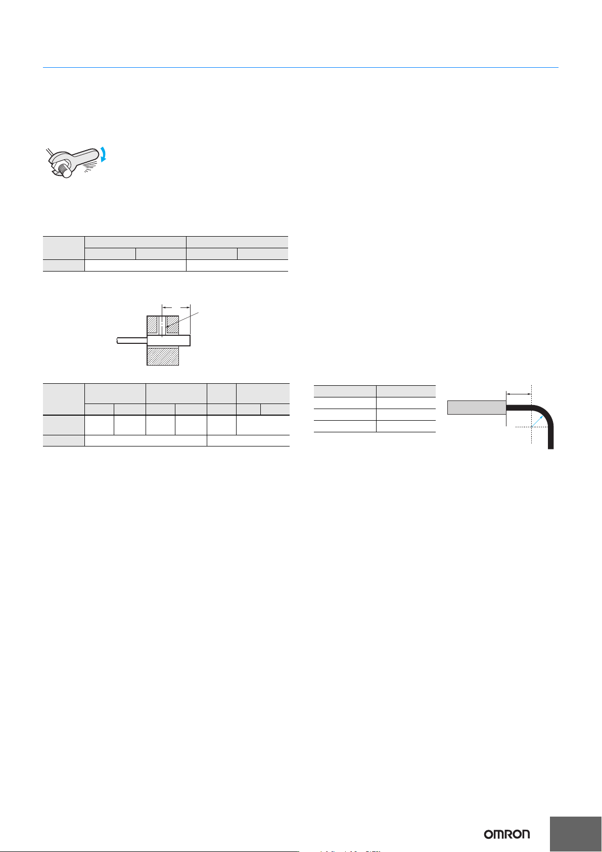
Tightening Force
〈Mounting threaded models (E2E-S@)〉
Do not tighten the nut with excessive force.
A washer must be used with the nut.
Note: 1.
Only use the provided nut and toothed washer.
Risk of changes in the sensing distance and damage if a different
material is used. If you lose the nut or washer, purchase an optional nut
set.
2. The following strengths assume washers are being used.
Note: Only use the provided nut.
〈Mounting unthreaded cylindrical models (E2E-C@)〉
* Excluding the operation indicator area.
When using a set screw, tighten it to the torque indicated in the table above.
Using a set screw in any area other than specified by the above dimensions
may result in fire or other occurrences due to damage to the internal circuit.
● Oil resistance
In accordance with our oil resistance standard, we test oil resistance
based on water insoluble oil (complies with test oil based on JIS
C0920, Appendix 1).
When water soluble cutting oil is used, durability varies due to the
dilution ratio and other factors.
Please test oil resistance using the actual oil that will be used.
● High-speed responsiveness
To obtain a better high-speed response, it is recommended that you
use the sensor at about 50% of the possible sensing distance.
A high-speed response may not be obtained with some sensing
object surfaces, materials, and shapes, or when the sensing distance
is greater than the set distance.
For the effects of materials, refer to Engineering Data on page 7.
● Protective Stainless-steel Spiral Tube
The spiral tube is in a fixed state and is intended to provide protection
against wire breakage due to shock from tools or other objects.
● Repeated cable bending tolerance
If you require repeated bending tolerance, use a sensor with a robot
(bending-resistant) cable or use a Connector Model together with a
connector cable that is specified for bending tolerance. (Example:
XS3F-M321-@@@-R)
Refer to Sensor I/O Connector on page 5.
● Block type mounting accessories
Due to differences in dimensional tolerances, these cannot be used
with older small diameter proximity sensors. (E2E-CR6@, E2E-
CR8@, E2E-C1@)
● Bending radius for mounting
If the cable is bent from its base, the resin on the surface of the cable
may peel off, however, this will not affect the protective structure or
sensing performance.
Avoid bending the cable at less than 10 mm from the base.
When bending the cable, refer to the table below.
● Total Cable Length
If you extend the cable length, use a conductor cross section of 0.14
mm
2
or greater and do not exceed a total length of 200 m for standard
cables or robot (bending-resistant) cables. It is assumed that an
independent metal conduit will be used.
Size M4 M5
Item Shielded Unshielded Shielded Unshielded
Tr 0.8 N·m 1 N·m
Size 3 dia. 4 dia.
5.4
dia.
6.5 dia.
Item
Shielded Unshielded Shielded Unshielded Shielded Shielded Unshielded
L *
9 to 21
mm
15 to 27
mm
8 to 21
mm
14 to 27
mm
8 to 21
mm
12 to 26 mm
Torque 0.2 N·m max. 0.4 N·m max.
Tr
Dimpled end of set screw (M3)
(Screw not provided)
L
R
10 mm
Sensor
* For a robot (bending-resistant) cable,
multiply the bending radius in the
above table by 1.7.
Cable diameter Bending radius*
3 dia., M4 7 mm
4 dia., 5.4 dia., M5 9 mm
6.5 dia. 12 mm