e2e_d115-e1_9_5_csm1012586.pdf - 第9页
E2E 9 I/O Circuit Diagrams Connection to I/O Connector (Connector Models, Pre-wired Connector Models) Operation mode Output specifications Model Timing chart Output circ uit NO NPN open- collector output E2E- @@@@ - @@ -…
E2E
8
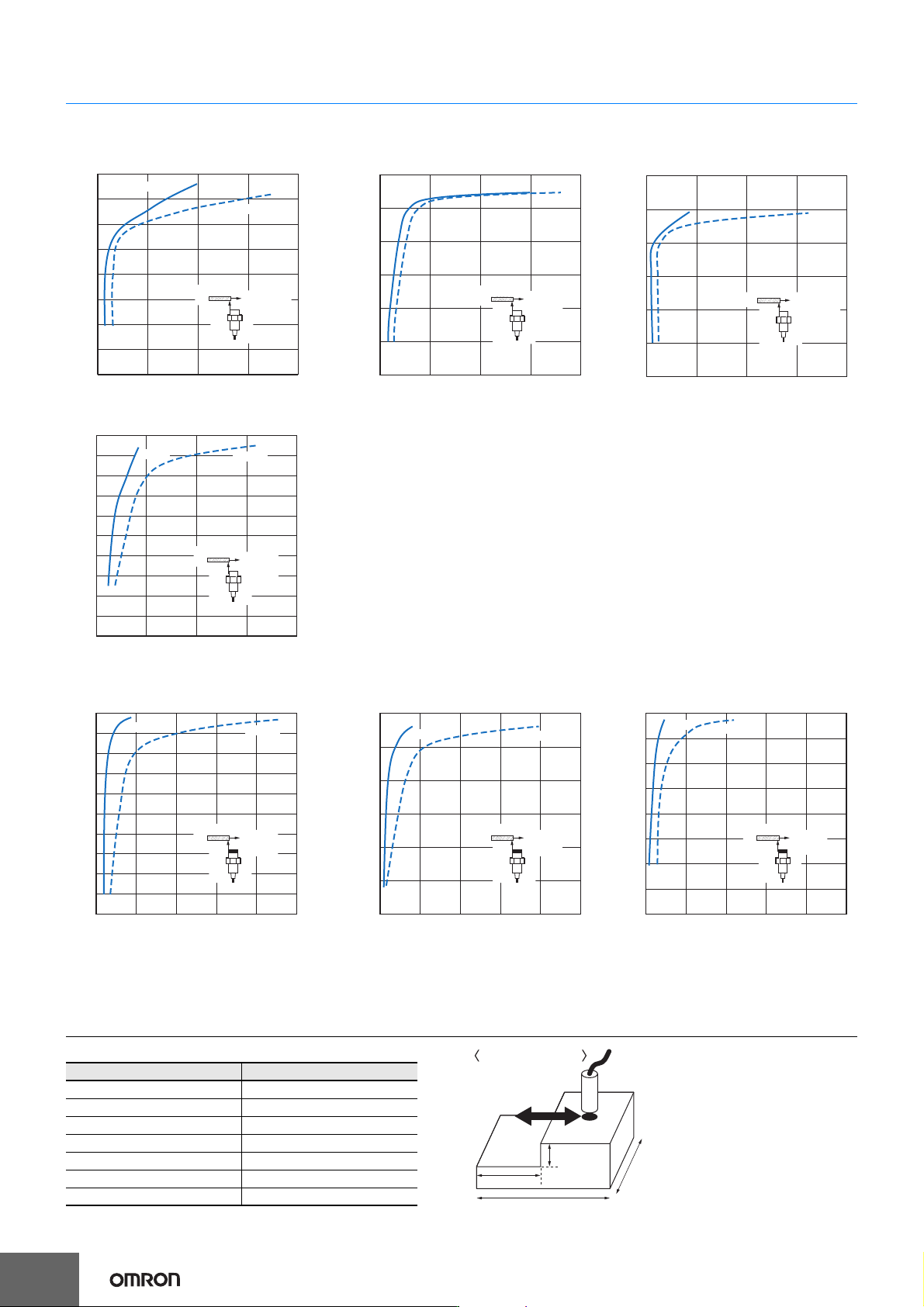
Distance - Horizontal Repeat Accuracy
Sensing distance vs. repeat accuracy graphs
By using within the sensor installation distance, the repeat accuracy stabilizes.
This data is reference data based on a standard sensing object, and is not a guarantee of performance.
The repeat accuracy varies depending on the effects of temperature, the material and surface condition of the sensing object, and other conditions.
Minimum measurement gap
Note:
Measured at constant temperature of 2
3ºC
using an iron sensing object of size
at least as large as standard sensing object (see right).
Shielded Models
E2E-C03SR8@/E2E-S04SR8@ E2E-C04S12@/E2E-S05S12@ E2E-C05S01@
E2E-C06S02@
Unshielded Models
E2E-C03N02@/E2E-S04N02@ E2E-C04N03@/E2E-S05N03@ E2E-C06N04@
Model Minimum gap (mm)
E2E-C03S/S04S 0.3
E2E-C03N/S04N 0.6
E2E-C04S/S05S 0.4
E2E-C04N/S05N 0.9
E2E-C05S 0.3
E2E-C06S 0.6
E2E-C06N 1.2
0.8
0.7
0.6
0.5
0.4
0.3
0.2
0.1
0 0.05 0.1 0.15 0.2
Repeat accuracy (mm)
12 VDC
24 VDC
Distance X (mm)
ON point
repeat
accuracy
@3 × 1 mm
X
1.2
1
0.8
0.6
0.4
0.2
0 0.05 0.1 0.15 0.2
12 VDC
24 VDC
Distance X (mm)
Repeat accuracy (mm)
ON point
repeat
accuracy
@4 × 1 mm
X
1.2
1
0.8
0.6
0.4
0.2
0 0.05 0.1 0.15 0.2
X
12 VDC
24 VDC
Distance X (mm)
ON point
repeat
accuracy
@5.4 × 1 mm
Repeat accuracy (mm)
2
1.8
1.6
1.4
1.2
1
0.8
0.6
0.4
0.2
0 0.05 0.1 0.15 0.2
12 VDC
24 VDC
Distance X (mm)
Repeat accuracy (mm)
ON point
repeat
accuracy
@6.5 × 1 mm
X
2
1.8
1.6
1.4
1.2
1
0.8
0.6
0.4
0.2
0 0.1 0.2 0.3 0.4 0.5
12 VDC
24 VDC
Distance X (mm)
Repeat accuracy (mm)
ON point
repeat
accuracy
@6 × 1 mm
X
3
2.5
2
1.5
1
0.5
0 0.1 0.2 0.3 0.4 0.5
12 VDC
24 VDC
Distance X (mm)
Repeat accuracy (mm)
ON point
repeat
accuracy
@9 × 1 mm
X
4
3.5
3
2.5
2
1.5
1
0.5
0 0.1 0.2 0.3 0.4 0.5
12 VDC
24 VDC
Distance X (mm)
Repeat accuracy (mm)
ON point
repeat
accuracy
@12 × 1 mm
X
30 mm
30 mm
15 mm
gap
Material: Iron
Size of test piece
E2E
9
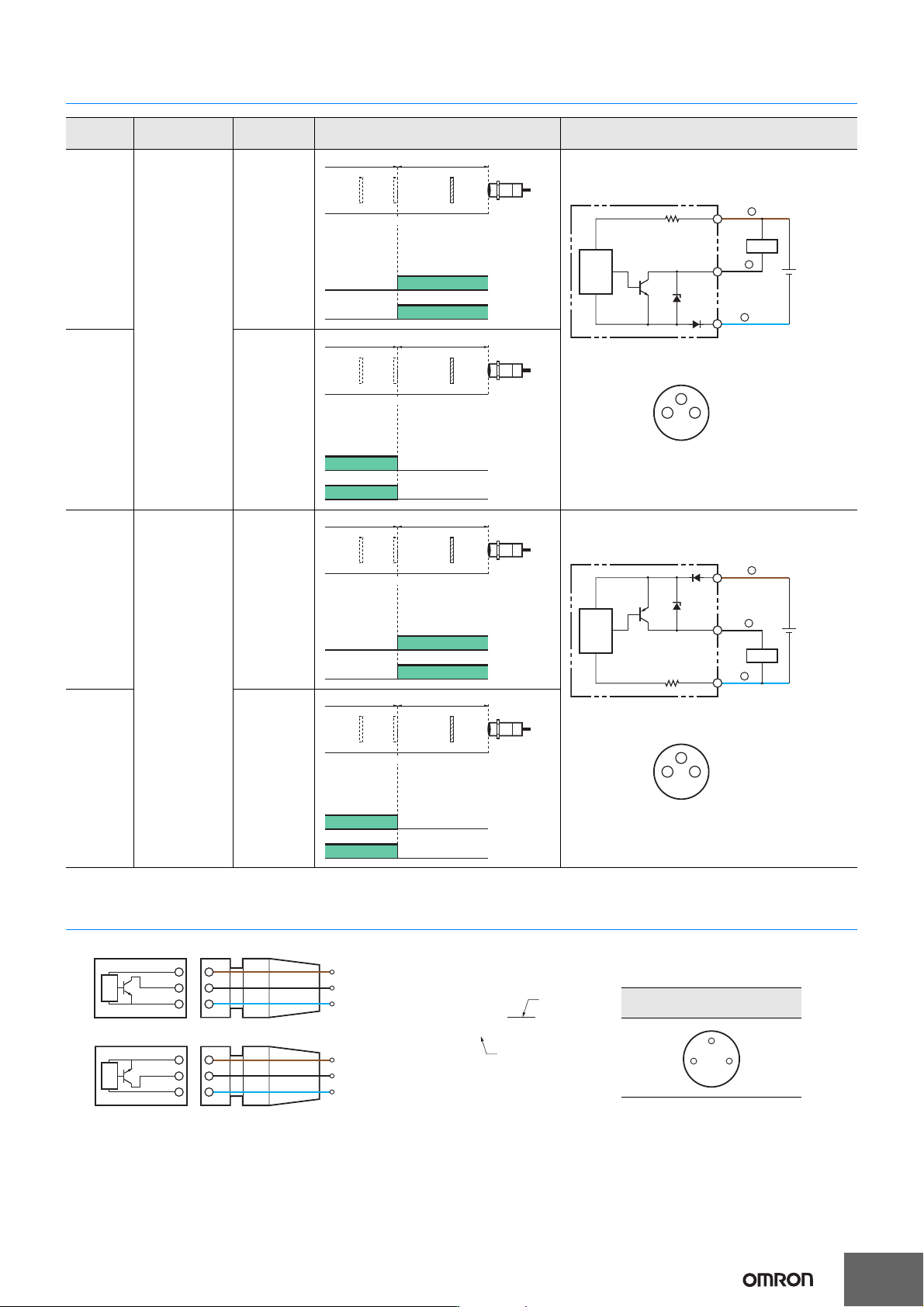
I/O Circuit Diagrams
Connection to I/O Connector (Connector Models, Pre-wired Connector Models)
Operation
mode
Output
specifications
Model Timing chart Output circuit
NO
NPN open-
collector
output
E2E-@@@@
-@@-C1
NC
E2E-@@@@
-@@-C2
NO
PNP open-
collector
output
E2E-@@@@
-@@-B1
NC
E2E-@@@@
-@@-B2
Sensing
object
Rated
sensing
distance
(%)
100 0
Sensing area
Non-sensing area
Proximity
Sensor
ON
OFF
ON
OFF
Operation
indicator
(yellow)
Control
output
Load
Brown
1
Black
Blue
Proximity
Sensor
main
circuit
10 to 30 VDC
31
4
Connector pin arrangement
M8
4
3
(%)
100 0
ON
OFF
ON
OFF
Proximity
Sensor
Sensing area
Non-sensing area
Sensing
object
Rated
sensing
distance
Operation
indicator
(yellow)
Control
output
Sensing
object
Rated
sensing
distance
(%)
100 0
Sensing area
Non-sensing area
Proximity
Sensor
ON
OFF
ON
OFF
Operation
indicator
(yellow)
Control
output
Load
10 to 30 VDC
Connector pin arrangement
M8
Proximity
Sensor
main
circuit
Brown
1
Black
4
Blue
3
31
4
(%)
100 0
ON
OFF
ON
OFF
Proximity
Sensor
Sensing area
Non-sensing area
Sensing
object
Rated
sensing
distance
Operation
indicator
(yellow)
Control
output
1
4
3
1
4
3
NPN
XS3F-M32@-3@@-R
1
4
3
1
4
3
PNP
02: 2 m
05: 5 m
1: Straight
2: Right-angle
Brown
Black
Blue
Brown
Black
Blue
Sensor I/O Connector
I/O connector cable,
connector arrangement diagram
31
4
E2E
10
Safety Precautions
Refer to Warranty and Limitations of Liability.
This product is not designed or rated for ensuring
safety of persons either directly or indirectly.
Do not use it for such purposes.
• Do not short the load. Explosion or burning may
result.
• Do not supply power to the Sensor with no load,
otherwise Sensor may be damaged.
Do not use this product under ambient conditions that exceed the
ratings.
● Design
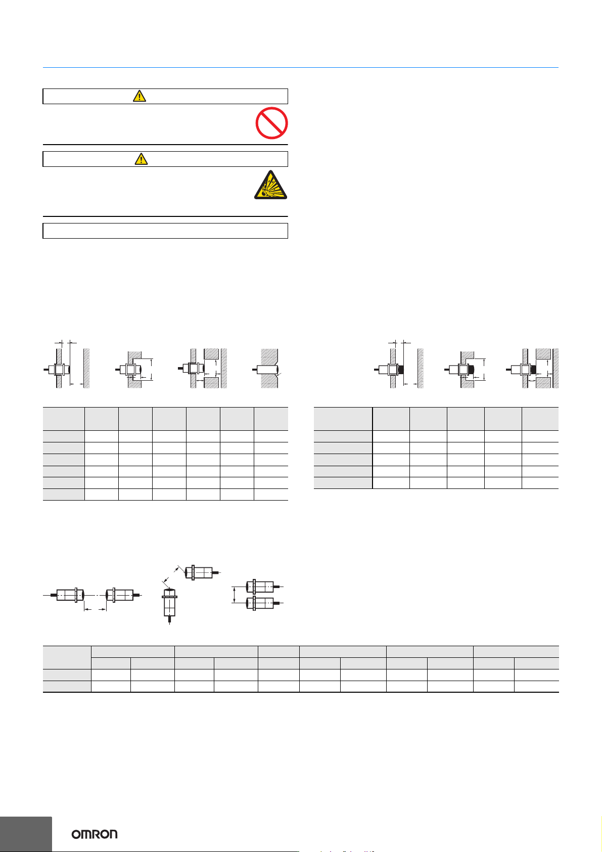
Influence of Surrounding Metal
When mounting the Sensor within a metal panel, ensure that the
clearances given in the following table are maintained. Failure to
maintain these distances may cause deterioration in the performance
of the Sensor.
〈Shielded Models〉
(Unit: mm)
〈Unshielded Models〉
(Unit: mm)
If mounted in a surrounding non-magnetic metal such as aluminum or copper, the sensing distance may shorten by about 40 to 50%.
If used in a recessed installation, take into consideration the effects of the material on the sensing distance.
Mutual Interference
When installing Sensors face-to-face or side-by-side, ensure that the minimum distances given in the following table are maintained.
Mutual Interference (Unit: mm)
* Values when the connector size is not taken into consideration.
WARNING
CAUTION
Precautions for Correct Use
Size
3 dia. 4 dia. 5.4 dia. 6.5 dia. M4 M5
Item
L 000000
m 353635
d 345.46.545
D 000000
n 810812810
c 000200
l
m
n
m
D
C
d dia.
L
Size
3 dia. 4 dia. 6.5 dia. M4 M5
Item
L 661266
m 69869
d 91224912
D 661266
n 16 20 24 16 20
l
m
n
m
D
d dia.
L
A
A
B
Size 3 dia. 4 dia. 5.4 dia. 6.5 dia. M4 M5
Item Shielded Unshielded Shielded Unshielded Shielded Shielded Unshielded Shielded Unshielded Shielded Unshielded
A 20 80 20 80 20 20 80 20 80 20 80
B * 15 60 15 60 15 15 60 15 60 15 60