力辰PV系列膏体粘度计说明书(英文版).pdf - 第4页
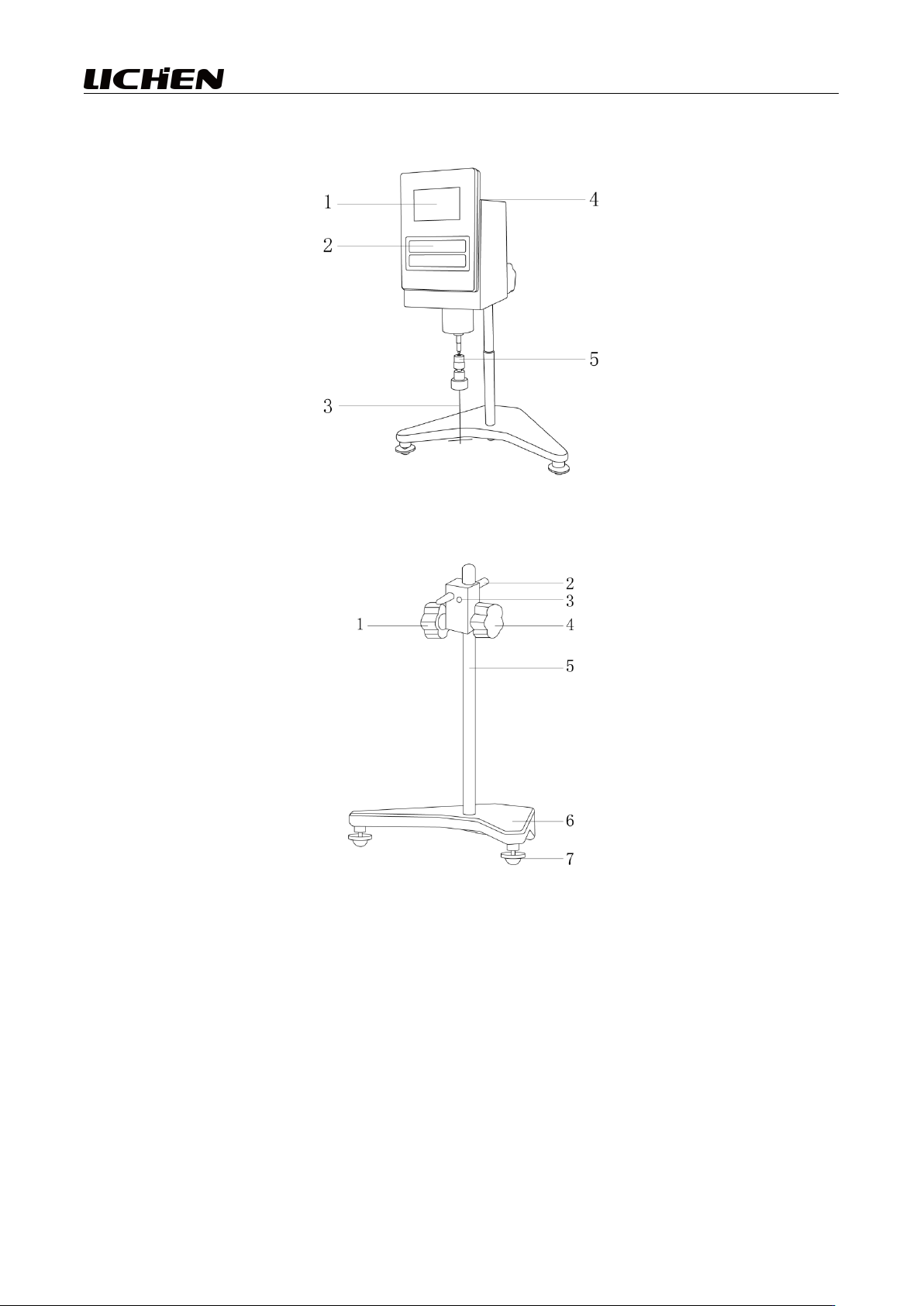
3 III. Product Portfoli o The overall structure of the machine (with the rotor installed) is shown in the figure: 1. Display screen 2. Operation butt ons 3. Rotor 4. V is cosity meter head level bubble indicator 5. Rotor…

2
I. Overview
The Lichen PV Series Paste Viscosity Meter is a digital rotary viscosity measurement
instrument specifically developed for high-viscosity, low-flow-rate, and thixotropic paste materials.
It is primarily designed to determine the dynamic viscosity of non-Newtonian paste materials,
addressing the testing challenges posed by conventional viscosimeters when handling viscous pastes,
gels, and thick pastes. This instrument is widely applied in laboratory research and development,
incoming material inspection, and finished product quality control scenarios, featuring an
aesthetically pleasing and compact design.
II. Product Specifications
Model
LC-PV-RVT
Source
AC100~240V 50/60Hz
Display mode
TFT color liquid crystal display
Measuring range
2K~100M mPa·s
Viscosity measurement accuracy
±1% (Newtonian fluid)
Repeatability error of viscosity
measurement
±0.5% (Newtonian fluid)
Rotor specifications
TA-TF rotor
Rotor speed
0.1~200 rpm (stepless/step-speed)
Recommended temperature
measurement range
0~60℃
Temperature measurement accuracy
±0.1℃
Net weight
7kg
Product dimensions (L×W×H)
290×330×580mm
3
III. Product Portfolio
The overall structure of the machine (with the rotor installed) is shown in the figure:
1. Display screen 2. Operation buttons 3. Rotor
4. Viscosity meter head level bubble indicator 5. Rotor connector
1. Machine head fixed handwheel 2. Machine head crossbar
3. Lift and tension adjustment screw (requires hex key) 4. Lift handwheel
5. Lift column 6. Main unit base
7. Main unit base level adjustment knob
4
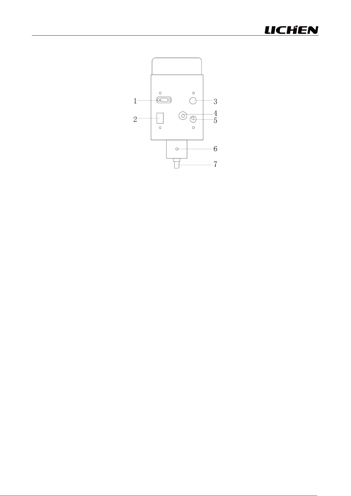
The rear layout of the instrument is shown in the figure (without the rotor installed):
1. RS232 interface, printer interface 2. Power switch 3. Temperature sensor probe interface
4. Horizontal bar interface 5. Power cord socket 6. Protective frame mounting hole
7. Yellow protective cap
IV. Installation and Use
1. Selection of the work environment
(1) The studio shall be kept clean and dry;
(2) The instrument should be placed away from sources of electromagnetic interference;
(3) The use of instruments shall be prohibited in areas posing an explosion hazard;
(4) Do not operate the instrument for extended periods in environments with high humidity or high
dust content.
2. Installation
(1) Open the packaging box and the instrument storage box, then, in accordance with the inventory
list provided in the appendix of this manual, conduct an inventory and inspection of all instrument
components;
(2) The instrument shall be installed on a workbench free of corrosive gases, strong electromagnetic
interference, and vibration;
(3) Insert the column into the corresponding hole of the main unit base; first, use a hex key to tighten
the bolts on the column (connected to the bottom of the base) to secure the column, then tighten the
screws on the front of the base to fix the column housing;
(4) Rotate the lifting handwheel to move the device up and down until it reaches its highest position.
If the lifting handwheel feels too tight or too loose during rotation, adjust the locking screw located
in front of the lifting base; it is advisable to tighten it slightly to prevent the viscometer head from
falling due to its own weight;
(5) Connect the head crossbar to the crossbar interface located behind the viscometer head, then