00191171-01.pdf - 第31页
Operating Manual Offset calibrat ion system for SIPL ACE 80 S15 / S2 0 / F3 / F 4 Edition 01/ 98 Page 31 of 47 • Set up the microscope in a secure position close to the machine. • Prepare the evaluation form ( print it o…
Offset calibration system for SIPLACE 80 S15 / S20 / F3 / F4 Operating Manual
Edition 01/98
Page 30 of 47
−
A conveyor width of 135 mm must be possible, i.e. the ceramic substrate centering and vacuum
PCB support must be removed
−
Feeder position must be free
1.5 Prerequisites for the Operating Personnel
Only qualified or adequately trained personnel are allowed to undertake the work described here. See
the definition in 0 in this regard. Furthermore, completion of a Siemens service technician course is
also a prerequisite.
2. Determining the Correction Values
2.1 Preparatory Work
•
Adjust the conveyor width to the width of the glass plate.
•
Setting up the feeder: Select the position (left/right) on the basis of the head which is to be meas-
ured and place the required component rail onto the feeder. Thoroughly clean the glass compo-
nents with glass cleaner and then use the suction device to place them onto the feeder. Their ori-
entation does not matter (the components are symmetrical). However, make sure the pin struc-
tures are underneath.
•
Set up the correct nozzles for your machine type:
Turret head of the SIPLACE S15: Type 617
Turret head of the SIPLACE S20 and SIPLACE F4: Type 720
Turret head of the SIPLACE F4/6: Type 820
IC head of the SIPLACE F range: Type 419
•
Clean the glass plate (use the glass cleaner in the case) and apply the adhesive pads. Do this by
carefully pulling off the white protective sheet without separating the adhesive pads from the trans-
parent backing sheet. Place the glass plate on a clean surface (the lettering appears as a mirror
image when seen from above). Line up the backing sheet of the adhesive pads with the right-hand
front edge of the glass plate (as seen in the transport direction). Each of the adhesive pads must
now be located approximately in the center of the individual placement positions. Press the adhe-
sive pads down firmly and carefully pull off the backing sheet. Make sure none of the adhesive
pads remain on the backing sheet. It is possible to place components onto the same adhesive pads
several times.
• Place a soft cloth in the reject bin.
Operating Manual Offset calibration system for SIPLACE 80 S15 / S20 / F3 / F4
Edition 01/98
Page 31 of 47
•
Set up the microscope in a secure position close to the machine.
•
Prepare the evaluation form (print it out if necessary).
2.2 Placing the Glass Components
•
Load the placement program corresponding to your machine. To do this, copy the GF, BE, PM and
LA files from the supplied diskette into the appropriate folders on the line computer’s hard disk.
•
Define the setup for the required station. Select feeder Fd
∼
LIN_30. Set the Glas16_16 component
for the turret head (all machines) or Glas32_32 for the IC head (F machines only).
•
From the ”Services” menu select the ”Packaging Box” command and enter a vibration time of 3000
ms there.
•
Save the data.
•
Allocate the respective placement program to the desired placement head, e.g. 16
Å
turret head,
36
Å
IC head.
•
Specify the job and send the data for the desired head to the required placement station.
•
Push the glass plate in the input conveyor above the light barrier. Placement starts.
•
You should repeat the placement procedure if several glass components are rejected. Ideally,
placement takes place with all 12 segments. However, evaluation is still possible even if up to 4
components have been rejected.
•
Only one component (13) is placed for the IC head. It makes sense to perform and evaluate this
placement several times in succession. The overall average of all placements is then used for the
offset correction.
2.3 Measuring the Offset
•
Remove the glass plate from the machine and put the plastic cover over it.
•
Turn over the glass plate (plastic cover downwards) and put it under the microscope.
•
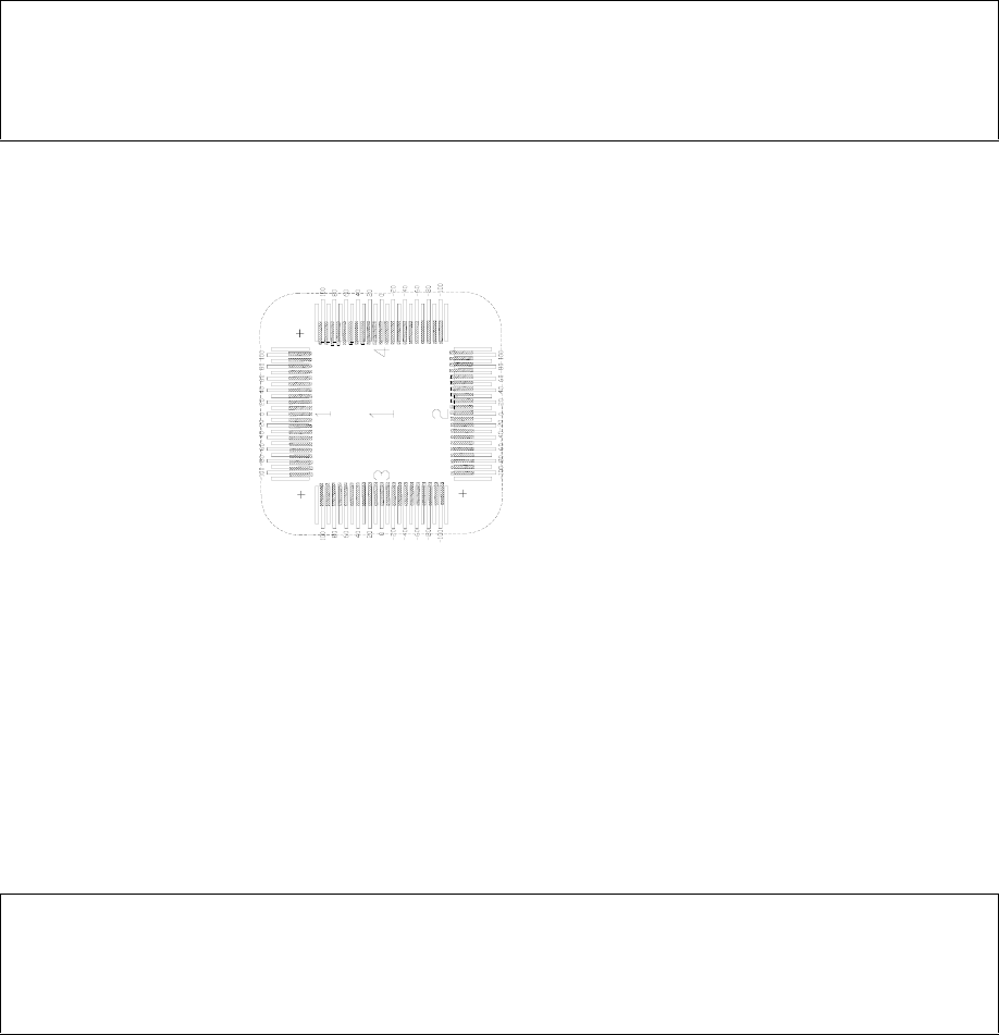
Start the measurement procedure with glass component no. 1, side 1. To do this, look at each of
the numbered sides (1 – 4) of the glass component to find the pin structure which best lines up with
a mark on the vernier scale of the glass plate. The principle is the same as with a caliper rule. In
the example shown on the next page (Fig. 2.3-1), the measurement values are +20 µm for side 1, -
80 µm for side 2, +20 µm for side 3 and -70 µm for side 4.
• Repeat the procedure for all the other glass components and enter the measured values in the ap-
propriate spaces on the evaluation form.
• With the IC head: Perform several measurements (repeat the placement several times).
Offset calibration system for SIPLACE 80 S15 / S20 / F3 / F4 Operating Manual
Edition 01/98
Page 32 of 47
Note
Do not mix up the sequence and sides of the glass components. Otherwise, the evaluation will be fal-
sified!
2.4 Evaluation
•
Use MS Excel to open the ANALYSIS.XLS file and fill in the ”General Information” (Machine No.,
User Name, Date). Click on the specific component and transfer each measured value in turn from
the evaluation form into the dialog boxes which appear.
Note
Manual evaluation (mathematical calculation without MS Excel) is also possible. Use the enclosed
evaluation form for this purpose.
•
Scroll to the right in the Excel window. The correction values are displayed under ”arithmethic
mean”.
•
Print out the Excel page with the mean values and place it to hand for entering corrections. Close
the Excel file by clicking on the ”Close all files” button.