stopper for HF-series for processing area 1.pdf - 第12页
1 Assembly instructions Special design Stopper for pl acement are a 1 (00166322-01) SIPLACE HF-series SIPLACE 06/2007 Edition 12 : Run the cables and the ho se like shown on the picture below . 1 1 : T wist the provided …
SIPLACE 1 Assembly instructions Special design Stopper for placement area 1 (00166322-01) SIPLACE HF-series
06/2007 Edition
11
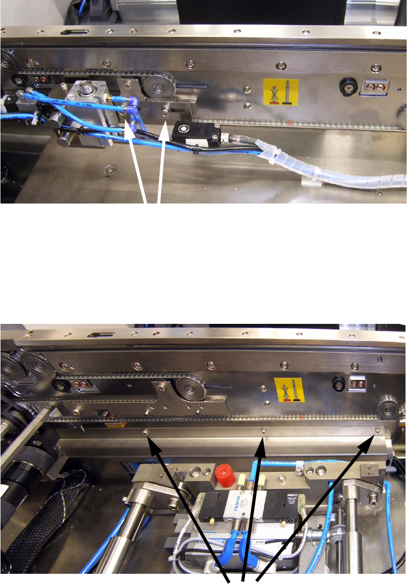
: Fit the stopper module with two screws and shims to the adapter. The stopper module can be
engaged in two positions.
1
1
1.7.2 Running and connecting thew cables and air hoses
1
Two screws
Three screws
1 Assembly instructions Special design Stopper for placement area 1 (00166322-01) SIPLACE HF-series SIPLACE
06/2007 Edition
12
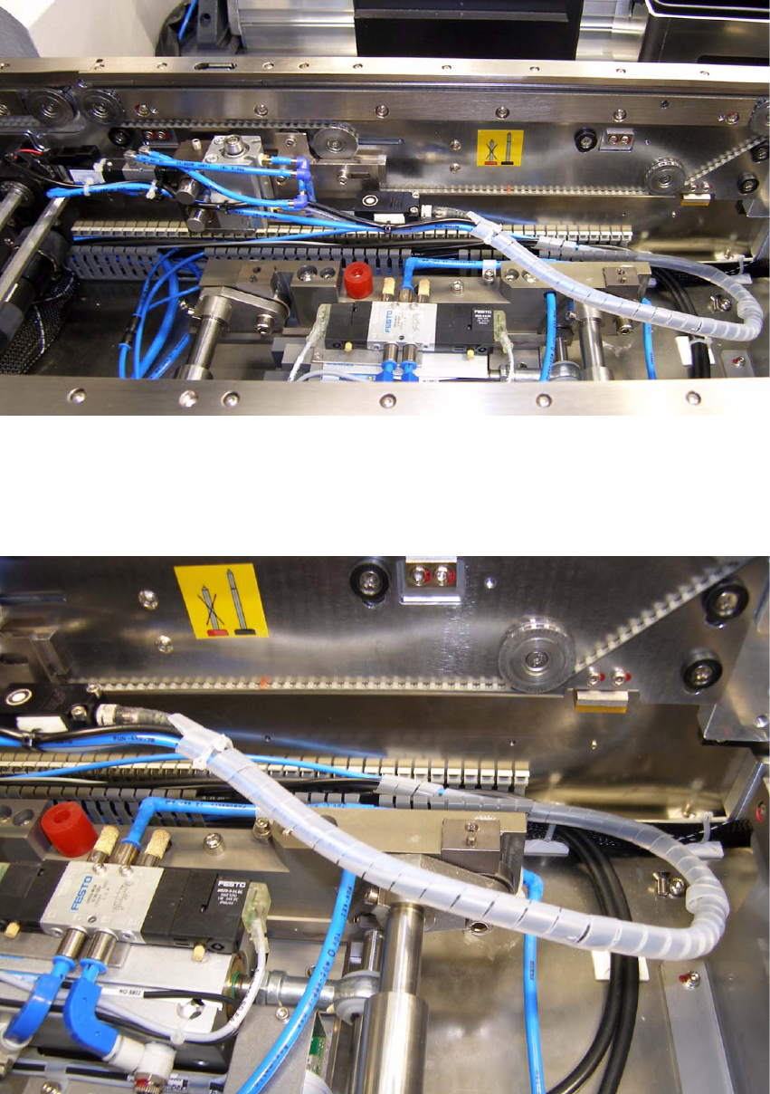
: Run the cables and the hose like shown on the picture below.
1
1
: Twist the provided cable cover around the cables and hose from the end of the module until
the cables are about 10 cm in the cable trench.
1
SIPLACE 1 Assembly instructions Special design Stopper for placement area 1 (00166322-01) SIPLACE HF-series
06/2007 Edition
13
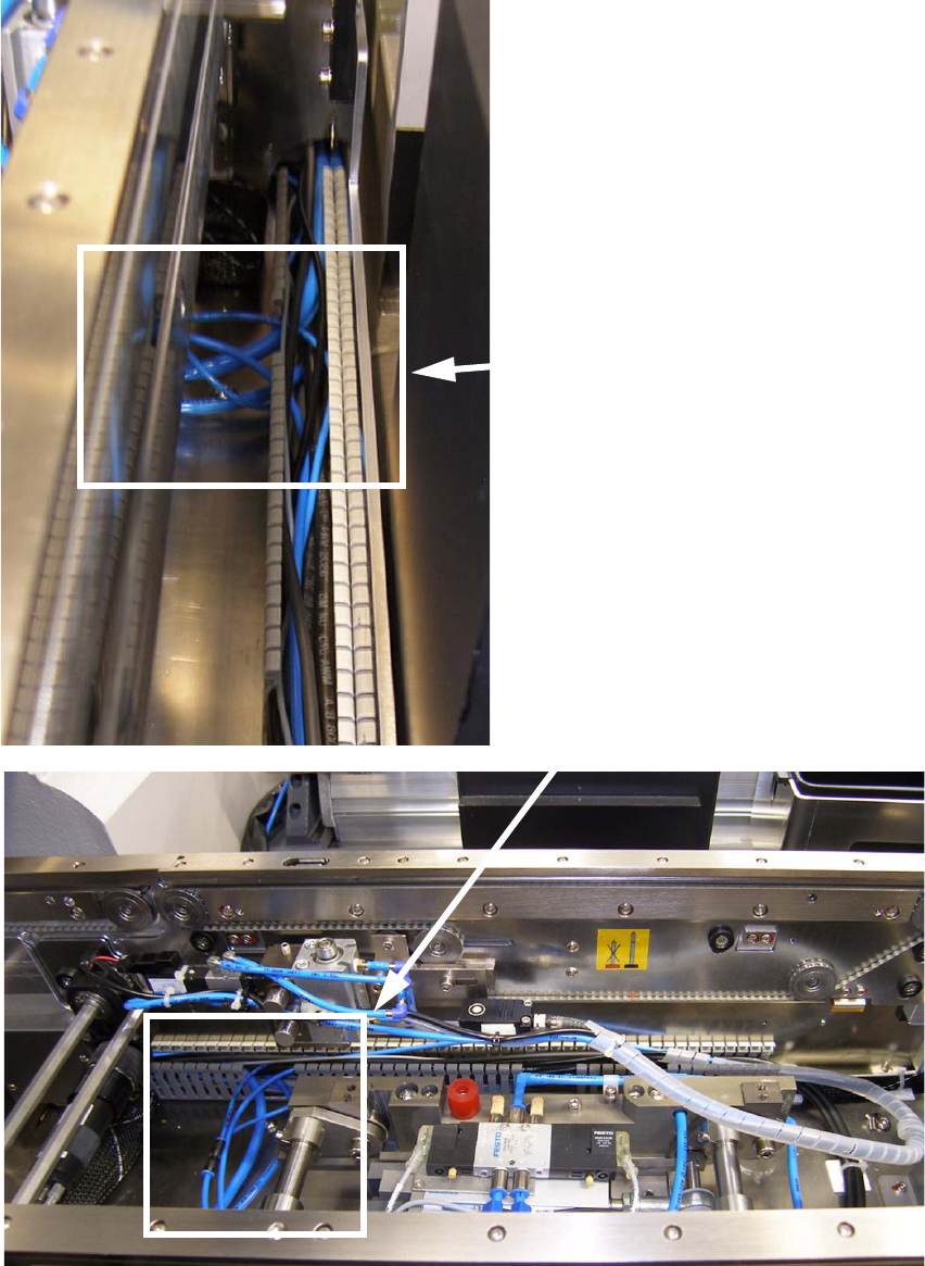
: Pull out the air hose like shown on the pictures below.
1
1