stopper for HF-series for processing area 1.pdf - 第25页
SIPLACE 1 Assembly instructions Special design Stopper for placement area 1 (00166322-01) SIPLACE HF-series 06/2007 Edition 25 1.1 1 Calibrating the PCB reference corner : Switch to SITES T and recalibrate the PCB refere…
1 Assembly instructions Special design Stopper for placement area 1 (00166322-01) SIPLACE HF-series SIPLACE
06/2007 Edition
24
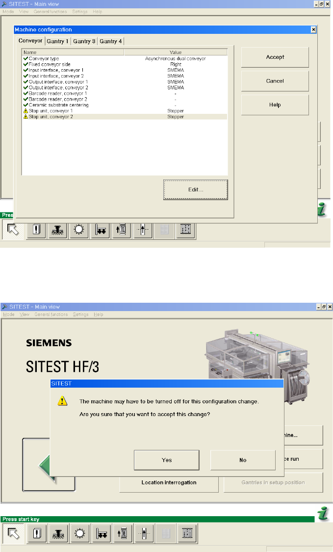
: Repeat the settings for conveyor 2 and click “Accept”.
1
: When you are asked, if you are sure that you want to accept this change, choose “Yes”.
1
: Shut down the machine and switch of the main switch.
SIPLACE 1 Assembly instructions Special design Stopper for placement area 1 (00166322-01) SIPLACE HF-series
06/2007 Edition
25
1.11 Calibrating the PCB reference corner
: Switch to SITEST and recalibrate the PCB reference corner for PA1.
Whenever the stopper position is changed, the PCB reference corner will have to be recalibrated
in SITEST. 1
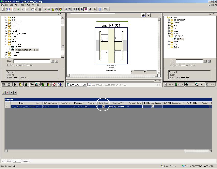
1.12 Description in SIPLACE Pro
: Set the flag "Long board" in the view "Line".
1
1
1
1
1
1 Assembly instructions Special design Stopper for placement area 1 (00166322-01) SIPLACE HF-series SIPLACE
06/2007 Edition
26
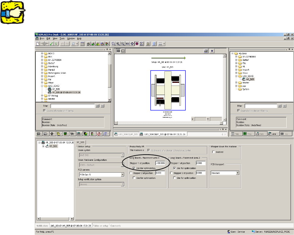
: Change to the actual setup.
: Fill out the offset values for the "long board - placement area 1" for "stopper 1 at position" and
set the flag for the optimization.
1
This value must be negative. 1
1
1
1
1
1
1
1
1
1
1
1