stopper for HF-series for processing area 1.pdf - 第27页
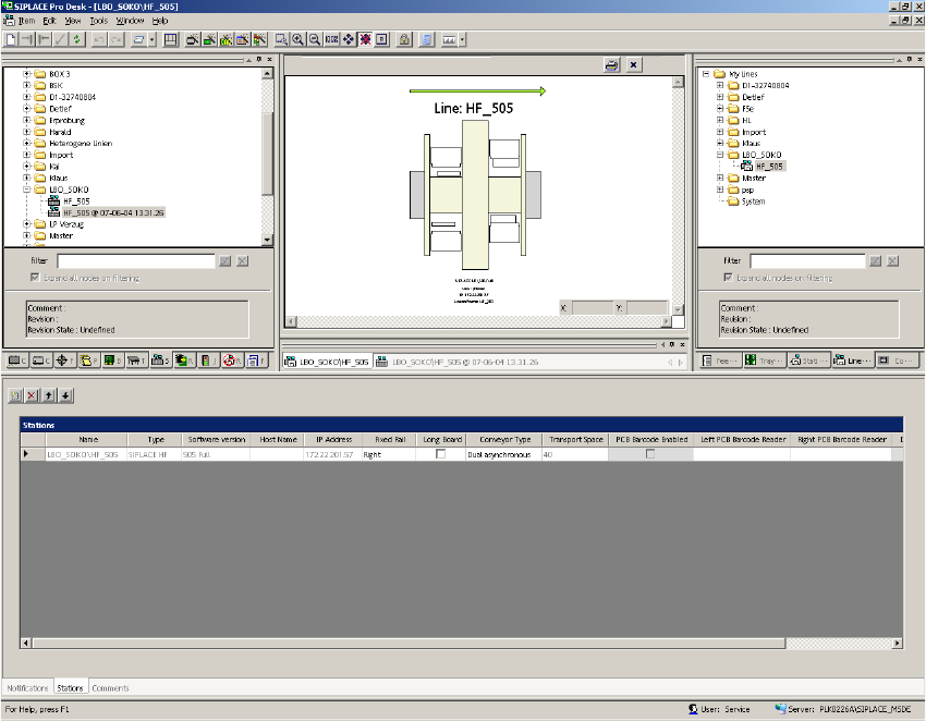
SIPLACE 1 Assembly instructions Special design Stopper for placement area 1 (00166322-01) SIPLACE HF-series 06/2007 Edition 27 : Change back to the view "Line" and disable the flag "Long board". 1 1 :…
1 Assembly instructions Special design Stopper for placement area 1 (00166322-01) SIPLACE HF-series SIPLACE
06/2007 Edition
26
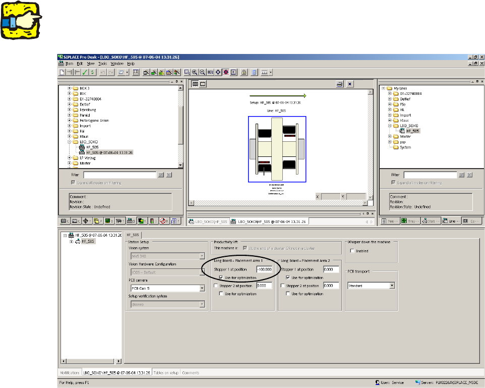
: Change to the actual setup.
: Fill out the offset values for the "long board - placement area 1" for "stopper 1 at position" and
set the flag for the optimization.
1
This value must be negative. 1
1
1
1
1
1
1
1
1
1
1
1
SIPLACE 1 Assembly instructions Special design Stopper for placement area 1 (00166322-01) SIPLACE HF-series
06/2007 Edition
27
: Change back to the view "Line" and disable the flag "Long board".
1
1
: Start the optimization and send the job to the SIPLACE machines.
1
1
1
1 Assembly instructions Special design Stopper for placement area 1 (00166322-01) SIPLACE HF-series SIPLACE
06/2007 Edition
28
1.13 Possible causes of error
1. The PCB camera does not find the fiducial or moves to the wrong position.
– Cause: The PCB reference corner was not recalibrated after the stopper was installed or its
position was changed.
1
2. The stopper does not move out.
– Causes:
- No compressed air connection or no compressed air available. A “Temporary drop in
compressed air supply” error message may appear on screen.
- The sensor on the stopper is defective.
3. The PCB is not detected.
– Cause: The sonar sensor is defective, was not calibrated or was incorrectly calibrated.
1.14 Removal
: Detach the plug-in connections on the conversion board and the compressed air connection.
: Remove the stopper module, assembly rail and the adapter plate.
: At the station, download the default conveyor firmware.
: Restart the placement machine.
1
1